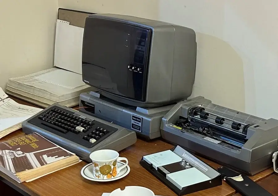
Supporting imagery
Model
Released on 18/10/1985 in America and 01/09/1986 in Europe.
Released on 15/07/1983 in Japan.
Motherboard
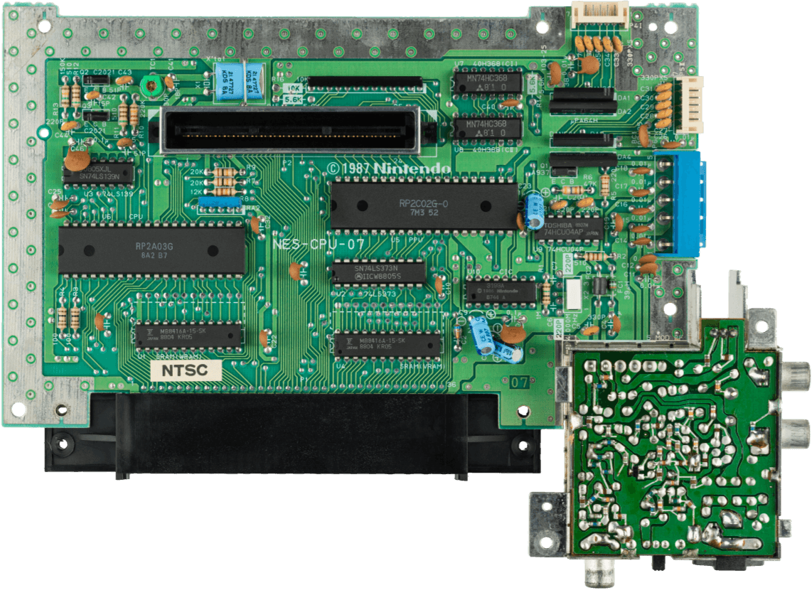
Showing the 'NES' variant.
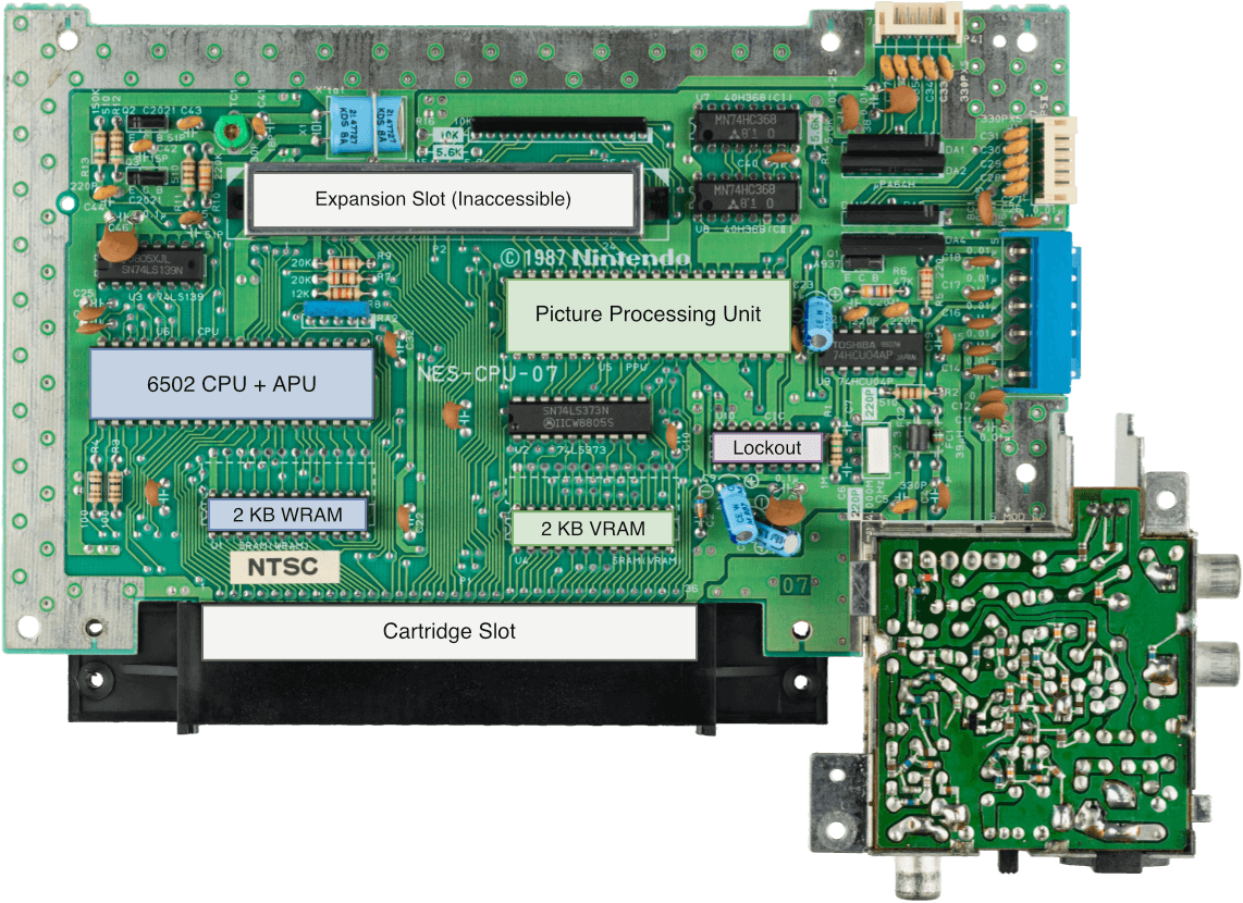
Diagram
A quick introduction
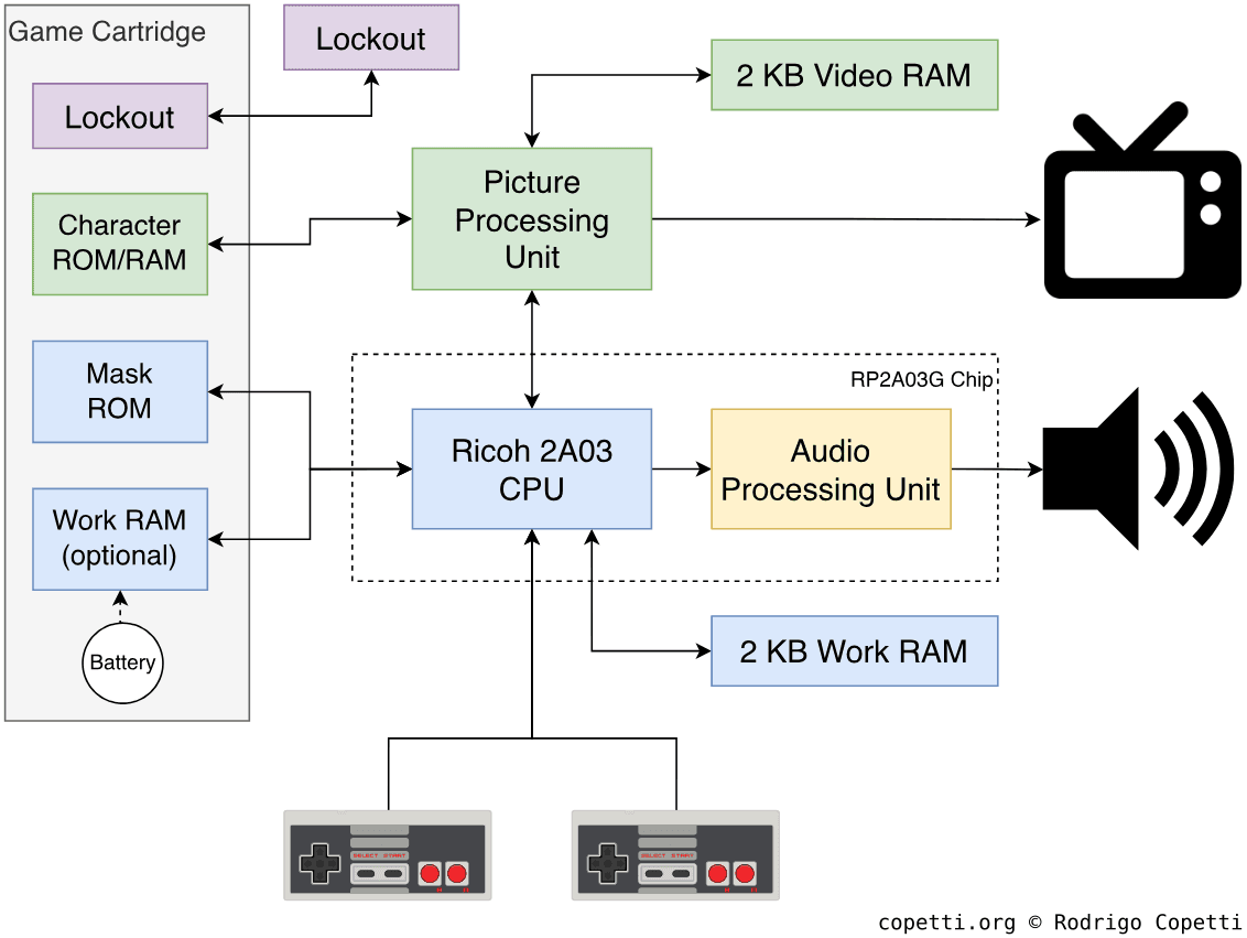
At first glance, the NES appears to be just another 6502 computer, with a sophisticated case and a controller.
And while this is technically true, let me show you why the CPU is not the central part of this system.
Models and variants

Nintendo ended up shipping lots of different variants of the same console across the world [1] and even though they all share the same architecture, many look dramatically different and some may include built-in accessories. So, to keep it simple for this article, I’ll focus on the two most popular revisions:
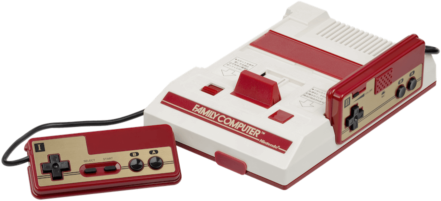
- The Family Computer (known as Famicom) was the first incarnation, but was only released in Japan. This toy-looking design features two non-removable controllers (of which the second controller bundles an internal microphone), a front socket for the light gun (called Zapper), RF video out (using NTSC-J signal) and extra pins in the cartridge slot to expand the audio capabilities.
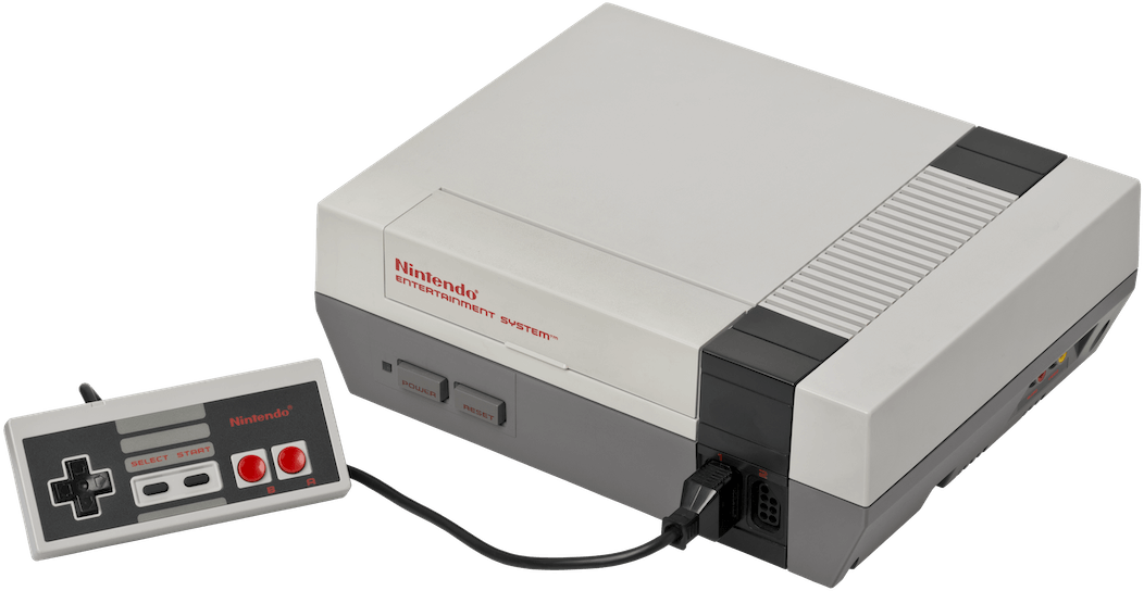
- The Nintendo Entertainment System (known as NES) was the redesigned edition for western audiences living in North America, Europe and Oceania; with a look and mechanism that match the common VHS/Betamax player. On the technical side, the controllers are now detachable (and microphone-lacking) and the video out has been improved with extra NTSC/PAL composite RCA connectors, although the audio expansion has been replaced with an anti-piracy subsystem. To top it off, the bottom of the case seals an ‘expansion port’ that was left unused, along with extra cartridge pins that communicate to that port [2].
Because the author grew up with the ‘NES’ name, I will default to using that term to refer to the console in general, but I will switch to ‘Famicom’ when referring to unique capabilities only found in the Japanese variant.
CPU
The NES’s CPU is a Ricoh 2A03 [3], which is based on the popular 8-bit MOS Technology 6502 and runs at 1.79 MHz (or 1.66 MHz in PAL systems). This is the central component that executes the code inside the game cartridge.
A bit of context
To understand the circuitry residing inside the NES’ motherboard, we must first take a look at the state of the industry at the time. Interestingly, the CPU market in the late 70s and early 80s was quite diverse.

If you were a startup aiming to build an affordable microcomputer for the western world, you had plenty of options available:
- The Intel 8080 (1974): A popular CPU featured in the MITS Altair 8800, the first ‘personal’ computer. It comes with a modest 8-bit data bus, a 16-bit address bus (enough to handle the necessary memory), and seven 8-bit registers. With capabilities like this, a line was drawn between the simple calculator and an actual computer.
- The Zilog Z80 (1976): Displeased with Intel’s direction and lack of investment in their CPU division, former engineers of the 8080 started their own company to produce an ‘unofficial’ successor, enhanced with more instructions, registers, and internal components. To top it off, it was sold at a lower price and could still execute 8080 programs [4]. The new CPU was well received by British firms Amstrad and Sinclair, as well as the Japanese Sega, among others.
- The Motorola 6800 (1974): Another 8-bit CPU designed around the same time. While a direct competitor of the 8080, the 6800 was programmed using a more sophisticated instruction set, albeit running at a slower clock speed [5]. Nevertheless, many do-it-yourself computer kits, synthesisers, and all-in-one computers included the 6800.
Faced with similar setbacks that Intel’s employees went through, engineers at Motorola grew frustrated with the company’s lack of interest in capitalising on the potential of the 6800 [6]. So, they joined a small but ambitious silicon firm, MOS, where they worked on a redesigned version of the 6800 - the MOS 6502. While incompatible with the rest, the new chip was much, much cheaper to produce [7] [8], and it was only a matter of time before iconic computer makers (Commodore, Tandy, Apple, Atari, Acorn, and so forth) chose the 6502 to power their machines.
Back in Japan, Nintendo needed something inexpensive yet familiar to develop for, so they selected the 6502. Ricoh, their CPU supplier, successfully produced a 6502-compatible clone.
Core functionality
To understand how capable this console is, let’s first check what the original MOS 6502 offers:
- The 6502 Instruction Set Architecture (ISA): MOS wanted to offer drastic improvements at the cost of compatibility with third-parties (especially Motorola) [9]. Thus, the 6502 instruction set still handles 8-bit words like the 6800 and others, but its programming is not cross-compatible.
- An 8-bit data bus and a 16-bit address bus. This was the typical combination for microprocessors of that era. Basically, it allows to operate data in chunks of eight bits without running out of memory locations (at least, too quickly).
- On paper, 16-bit addresses means the 8-bit CPU will need extra cycles to process the extra size. However, thanks to MOS’s new addressing modes (explained further down), these penalties were alleviated without requiring too much circuitry.
- Three general-purpose registers (
X,YandA), which may look constrained when compared to larger register files. This decision reduces costs but also means the CPU would need to move memory around more frequently. With the 6502,XandYare called ‘index registers’ and are used to address memory, whileAis directly connected to the ALU and dedicated to arithmetic operations.- By comparison, the Motorola 6800 has two accumulator registers and only one index register, which allows for a simpler instruction set.
- An 8-bit Arithmetic Logic Unit (ALU), which comes as no surprise for an 8-bit CPU, but it’s worth pointing out that others like the Zilog Z80 came with a 4-bit ALU instead.
- An 8-bit stack pointer: This is usually beyond the scope of this analysis, but I wanted to highlight it due to its significant deviation from Motorola’s design. As mentioned before, the address bus is 16-bit, so a memory-dependent component like the stack pointer should ideally match that size. However, MOS opted to halve the requirement and store the stack within a fixed memory range. Nevertheless, it was a clever cost-saving measure, as it encouraged developers to adopt efficient programming techniques to maximise the stack space.
- 13 addressing modes. Thanks to the inclusion of two index registers, programs can choose between many formats for accessing memory. Some are optimised for zero-page addressing (the first 256 bytes of memory), while others encode a lookup address to retrieve the actual address dynamically. In the end, this helped save as many memory cycles as possible, at the cost of complexity.
- By comparison, the 6800 and its single index register only offer seven addressing modes, with no equivalent for the flexible types.
As you can see, the remarkable engineering behind the 6502 allowed MOS to sell a compelling product at an extremely affordable price.
Ricoh’s licensing enigma
How Ricoh managed to clone the 6502 isn’t clear to this day. One would expect MOS to have licensed the chip design to Ricoh, but there are many contradictions to this:
- Both Ricoh’s and MOS’s variants feature the same layout, but Ricoh’s contains severed buses (disabling certain functions) [10]. I go into more detail later.
- A document explicitly stating that MOS licensed the 6502 to Ricoh is yet to be found.
- An article published in 2008 by Nikkei Trendy states that Ricoh licensed from Rockwell, an authorised chip manufacturer [11]. However, it’s debatable whether a second source was able to provide IP to a third party, much less with MOS’s approval.
- It wouldn’t be the first time Nintendo got away with circumventing IP rights, as Ikegami Tsushinki v. Nintendo ruled in Japan that Nintendo didn’t own the code of the original Donkey Kong [12].
Scrapped functions
The Ricoh 2A03 omits the Binary-Coded Decimal (BCD) mode originally included in the 6502 [13]. BCD encodes each decimal digit of a number as a separate 4-bit binary. The 6502 uses 8-bit ‘words’ - meaning that each word stores two decimal digits.
As an example for the curious, the decimal number 42 is represented as:
0010 1010in binary.0100 0010in BCD.
We could go on and on talking about it, but to give an outline: BCD is useful for applications that require treating each decimal place separately (for instance, a digital clock). However, it requires more storage since each 8-bit word can only encode up to the decimal number 99 - whereas traditional binary can encode up to 255.
In any case, Ricoh deliberately broke BCD mode in its chip by severing the control lines that activate it. This was presumably done to avoid paying royalties to MOS, since BCD was patented by them (and the legislation that enabled copyrighting integrated circuit layouts in the United States wasn’t enacted until 1984 [14]).
Memory
Both Ricoh 2A03 and MOS 6502 feature an 8-bit data bus and a 16-bit address bus, which allow them to access up to 64 KB of memory. So, how did Nintendo fill that memory space?
On one side, the motherboard contains a chip providing 2 KB of Static RAM (SRAM) [15]. Nintendo calls this area ‘Work RAM’ (WRAM) and can be used to store:
- Variables for handling the game state and/or to look up information.
- The ‘stack’, which temporarily saves register values while the CPU is executing subroutines.
- A ‘buffer area’ so the CPU can copy large data between two locations.
On the other side, the components of the system are memory-mapped [16], meaning that they are accessed using memory addresses and therefore occupy part of the CPU’s address space. Consequently, the Ricoh 2A03’s memory space is filled with addresses pointing to the game cartridge, WRAM, the PPU, the APU and two controllers (don’t worry about each component, as they are explained throughout this article).
Segmentation Fault
Inherited from MOS’ design, this console also features a special ‘anomaly’ called Open Bus: If an instruction tries to read from an unmapped or invalid address, the last value read is supplied instead [17]. If this goes unhandled by the program, execution may continue in an unpredictable state.
Cartridge/game data
Just in case you don’t know, NES games are distributed in the form of cartridges, and the cartridge’s buses connect directly to the CPU.
Nintendo wired up the cartridge lines in a way that only 49120 Bytes (~ 49.97 KB) of cartridge data can be accessed [18]. Now, what do I mean by ‘cartridge data’? Well, any chip connected to those buses, for instance:
- A Program ROM where the game’s program resides. This excludes the graphics data, as you’ll later see in the ‘Graphics’ section. Naturally and unlike the other chips, this one is mandatory.
- RAM chips to extend WRAM.
- A battery-packed RAM chip to store saves.
The existence of different combinations stems from the fact that the CPU doesn’t care about what kind of component it is reading from; it only sees memory locations. So, it is up to game studios to choose (or devise) a feasible layout to fit in their game.
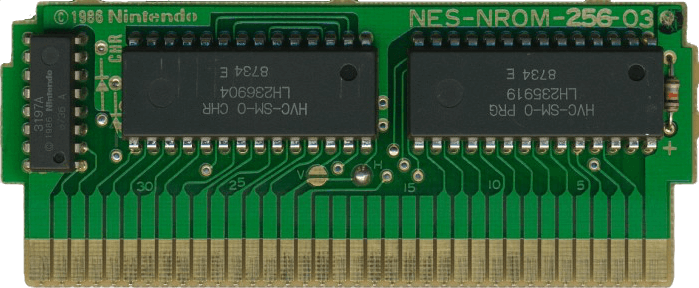
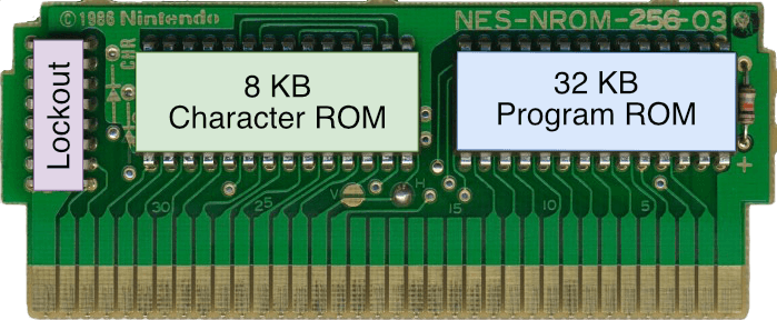
For example, Nintendo’s ‘Super Mario Bros’ used a layout they call NES-NROM-256 and consists of 32 KB of program ROM and 8 KB of ‘Character ROM’ for graphics (we’ll see more about it in the ‘Graphics’ section) [20]. NES-NROM-256 was also prepared to house up to 3 KB of extra WRAM, though the game doesn’t make use of it.
Going beyond existing capabilities
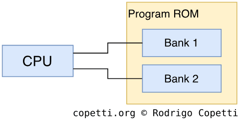
One of the major limitations of 16-bit address buses (affecting 3rd and 4th-generation consoles) is their compact address space. Nowadays, 32-bit computers can address up to 4 GB of memory (and 64-bit machines lavishly enjoy up to 16 exabytes), so this is no longer a concern, but back then, the NES only had a 64 KB address space, and a significant portion was consumed by the memory-mapped hardware (something competitors avoided).
So, did this mean that game studios could only develop games that stayed within the 49.97 KB limit? Absolutely not! If history has taught us anything, it is that there’s always a clever solution to a challenging problem, and this issue was tackled with a Mapper.
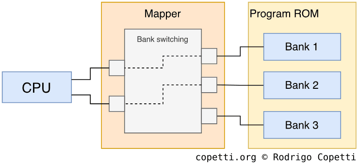
A mapper is an extra chip included in the cartridge that sits between the memory chips and the console’s address lines. Its primary job is to extend the address space, allowing developers to fit more chips. This is achieved through bank switching: memory addresses are grouped into banks, and the mapper provides switches (controlled via memory addresses) to alternate between them. Now, the CPU still perceives the same amount of memory, so it is the game (programmed with a mapper present) in charge of operating it. Due to their cost-effectiveness, mappers were the order of the day in 80s-to-early-90s technology.


Back to the NES, games like ‘Super Mario Bros 2’ and ‘Super Mario Bros 3’ shipped with the ‘MMC3’ mapper (made by Nintendo) in their cartridges. For comparison, MMC3 provided up to 512 KB of space for the Program ROM, up to 256 KB for Character memory and up to 8 KB for extra WRAM [22]. You can now see why ‘Super Mario Bros 3’ differs significantly in quality compared to the first instalment.
All in all, while this console may appear limited while examining its internal features, Nintendo made sure it could adapt as technology evolves. On the other side, while this technique helped to keep the costs of the console down, it shifted part of the burden to the game cartridge. So, game quality and cartridge costs were two concerns game studios had to balance.
Graphics
Graphics are generated by a proprietary chip called the Picture Processing Unit (PPU). This is one of the chips that gives the NES an identity. To put it another way, since anyone could pick up a 6502 at a hardware store, why is the NES any different from, say, an Apple II or a Commodore 64? Well, what distinguishes the NES from other machines are the chips that surround the CPU: the PPU and the APU. These make up the NES’ unique graphics and audio capabilities, respectively.
That being said, the PPU renders 2D graphics called sprites and backgrounds, outputting the result to the video signal.
Organising the content
To render something on the screen, the PPU must know which graphics to draw, where on the screen to place them, and how to draw them (i.e., which palette to use).
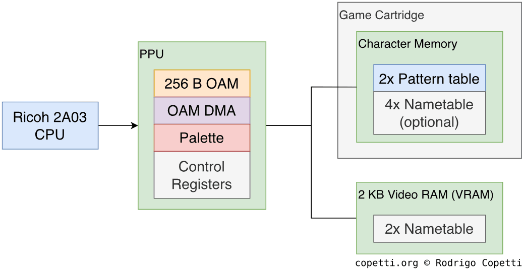
To answer these questions, the PPU came pre-programmed with a different memory layout that looks for specific types of data:
- Graphics data is pulled from the game cartridge, which contains a dedicated chip called Character memory that stores the 2D drawings (called tiles) organised into a data structure named Pattern table. Character memory materialises in the form of ‘Read-Only Memory’ (ROM) or ‘Random-Access Memory’ (RAM), depending on whether the game ships with an immutable set of graphics or the CPU must intervene, respectively.
- The PPU addresses up to 8 KB of Character memory organised into two groups of 4 KB each.
- Meta-data telling the PPU ‘where’ and ‘how’ to draw graphics is found in other areas:
- The motherboard houses 2 KB of SRAM specifically for graphics-related data. Nintendo calls this space Video RAM (VRAM), and it stores two data structures called Nametables.
- The PPU embeds 256 bytes of Dynamic RAM (DRAM) to store the Object Attribute Memory (OAM).
- Lastly, the PPU also bundles 4 bytes of memory to define colour palettes.
Don’t worry about the new terminology; the meanings of these data structures are discussed step by step in the following paragraphs.
Constructing the frame
As with its contemporaries, this chip is designed for the behaviour of a CRT display. There is no frame buffer as such: the PPU will render in step with the CRT’s beam, building the image on the fly.
The PPU draws frames with a fixed dimension of 256x240 pixels [23]. Alas, due to the discrepancies in analogue video standards across the world, the image will differ in appearance depending on the region of the appliance (NTSC or PAL) from which it is displayed. In a nutshell, NTSC televisions will crop the top and bottom edges to accommodate overscan (only ~224 scan-lines are visible), so these edges are considered ‘danger zones’ by developers when deciding where to place elements in the game. On the other hand, PAL tellies won’t crop the edges but will show extra black bars to fill the taller signal (PAL uses 288 scan-lines).
Behind the scenes, the frame output by the PPU is composed of two different layers. For demonstration purposes, let’s use Super Mario Bros. to show how this works:
Tiles


To begin with, the PPU uses tiles as a basic ingredient for producing sprites and backgrounds.
The NES defines tiles as basic 8x8 pixel maps, these are stored in Character memory (residing in the game cartridge) and organised into a big data structure called Pattern Table [24]. Each tile occupies 16 bytes, and a Pattern table houses 256 tiles [25]. Since the PPU addresses up to 8 KB of Character memory, it can access up to two Pattern tables.
Inside a tile, each of its pixels is encoded using a 2-bit value, which references one of four colours from a palette. Programmers can define up to eight palettes (four for the background and four for sprites). The colours referenced on each palette point to a ‘master palette’ consisting of 64 colours [26], representing all the colours that this console can produce. Each palette is made of four colours, with one reserved for transparent.
To start drawing something on the screen, games populate a set of tables with references to tiles stored in Character memory. Each table is responsible for one layer (sprite or background) of the frame. Then, the PPU reads from those tables and composes the scan-lines that will be beamed by the CRT gun.
I will now explain how each layer/table works and how they differ in terms of functionality.
Background Layer


The background layer is a 512x480 pixel map containing static tiles [27]. You may recall that the viewable frame is much smaller, so the game decides which part of the layer is selected for display. Games can also shift the viewable area during gameplay; that’s how the scrolling effect is accomplished.
To save memory, groups of four tiles are combined into 16x16-pixel maps called blocks, in which all tiles share a colour palette.
Nametables (stored in VRAM) specify which tiles to display in the background layer. The PPU looks for four 1024-byte Nametables, each one corresponding to a quadrant of the layer. However, only 2 KB of VRAM is available! Meaning that only two Nametables can be stored without additional hardware provided by the cartridge. Yet, the remaining two still have to be addressed somewhere: most games simply point the remaining two where the first two are (this is called mirroring).
Although this architecture may seem flawed at first, it was designed to minimise costs while ensuring simple expandability: if the game requires a wider background, just fit extra VRAM in the cartridge.
Moving on, the last bytes of each Nametable store a 64-byte Attribute table that specifies which colour palette is assigned to each block [28].
Sprite Layer
Sprites are tiles that can move around the screen. They can also overlap one another, or appear behind the background. The viewable graphic is determined by its priority value (similar to the concept of ‘layers’ in traditional graphic design software).
The Object Attribute Memory (OAM) table specifies which tiles will be used as sprites [29]. In addition to the tile index, each entry includes an (x,y) position and several attributes (colour palette, priority and flip flags). This table resides in a 256-byte DRAM located within the PPU chip.
The CPU can populate the OAM table, but this process can be slow in practice and risks corrupting the frame if not timed correctly. As a result, the PPU contains a small component called Direct Memory Access or ‘DMA’ which can be programmed (by altering the PPU’s registers) to fetch the table from WRAM. With DMA, the table is guaranteed to be uploaded when the next frame is drawn; however, the CPU will be halted during the transfer!
The PPU is limited to eight sprites per scan-line and up to 64 sprites per frame. Luckily, the scan-line limit can be partially circumvented thanks to a technique called ‘OAM order rotation’, in which the game manually alters the order of entries in OAM. This makes the PPU render a different sprite set at each frame, and the speed of the CRT beam will trick the user into seeing more sprites than allowed. However, they will also appear to flicker on-screen.
Background Split

Before we move on, there’s an additional detail worth mentioning. If you play Super Mario Bros, you’ll notice that when Mario moves, the scene scrolls without a hitch. However, you’ll also observe that the top area (where the stats are) remains static even though both portions belong to the same background layer! So, what is happening here? Well, the game is altering the scrolling values mid-frame to show the overworld and the stats (residing in a fixed portion of the background) at the same time. The NES doesn’t provide this feature natively, but the game deduces the timings by observing the state of the PPU (manifested through its status register [30]).
To accomplish this, games use a technique called Sprite 0 Hit. Super Mario Bros instructs the PPU to render a dummy sprite behind the coin, this happens to be the first sprite drawn within the frame. After the PPU beams it, it updates its status register with a flag to indicate that the first sprite (a.k.a ‘sprite 0’) has been drawn. Meanwhile, the game continuously checks mid-frame whether the sprite 0 status has been flagged (a.k.a ‘hit’). When this occurs, the game updates the scrolling value of the background table to align it with Mario’s position.
Overall, ‘Sprite 0 Hit’ is a very delicate procedure, as it’s easy to mess up the timings (sprite 0’s flag is not cleared after polling it, which leads to ‘duplicated’ positives [31]). Furthermore, as this routine repeats indefinitely, it can be quite costly (in terms of CPU cycles) to execute. On the bright side, later mappers took over this function by employing automatic interrupts that are triggered whenever an arbitrary scan-line is hit [32] (a much more efficient technique), which significantly improved the visual capabilities of Super Mario Bros 3, for instance.
Result
Once the frame is finished, it’s time to move on to the next one!
However, the CPU can’t modify any table currently in use by the PPU, otherwise, artefacts may show up on the screen. So, when all scan-lines are completed, the PPU triggers the Vertical Blank (V-Blank) interrupt on the CPU [33]. This notifies the game that it can start updating the tables without tearing the picture currently displayed. At that moment, the CRT’s beam is pointing below the visible area of the screen, into the overscan (or bottom border area).
Only a handful of PPU registers can be updated outside the V-Blank window [34], which explains the ability to scroll the background layer mid-frame.
Secrets and limitations
If you’re thinking that a frame-buffer system with memory allocated to store the full frame would have been preferable: RAM costs were prohibitively high, and the console’s goal was to be affordable. Let me now show you why this design still proved to be both efficient and flexible.
Multi-Scrolling


Some games require the main character to move vertically; therefore, the nametable is set up with horizontal mirroring. Other games need their character to move left and right, and so implement vertical mirroring instead.
Either type of mirroring allows the PPU to update background tiles without the user noticing, as there is ample space to scroll while new tiles are being rendered at a distance.
But what happens if the character needs to move diagonally? The PPU can scroll in any direction; however, without extra VRAM, the edges are forced to share the same colour palette (remember that tiles are grouped in blocks).
This explains why some games like Super Mario Bros. 3 show strange graphics at the right edge of the screen while Mario moves (the game is set up for vertical scrolling) [35]. It’s possible that they needed to minimise the hardware cost per cartridge, as this game already bundles a powerful mapper.
As an interesting fix: the PPU allowed developers to apply a vertical mask on top of tiles, effectively concealing part of the glitchy area.
Tile-Swapping


Another remarkable feature of Super Mario Bros. 3 is the number of graphics it can display.
This game displays more background tiles than strictly permitted. How does it achieve this? By taking two screen captures at different times while the display is generated, we can see that the final frame is actually composed of two distinct frames.
This is another wizardry of the MMC3 mapper, which not only addresses extra space in the Program ROM, but also extends the Character ROM space by connecting two separate Character chips. By determining which part of the screen the PPU is requesting, the mapper redirects to one chip or the other, thereby allowing more unique tiles on-screen than was originally supported [36].
Curious behaviour
Throughout my research, I came across many interesting articles that explain unusual behaviour of the PPU, so I thought to mention a few here:
- Unlike the Master System’s VDP, which generates RGB colours that are subsequently encoded into NTSC/PAL signals for broadcasting, the NES’ PPU does all at once [37]. Hence, there isn’t a one-to-one correspondence between the colours of the PPU master palette and the standard RGB colourspace (widely adopted by present technology). This leaves some room for interpretation and, as a consequence, various emulators may display a different palette.
- The discrepancies between RGB palettes can be observed using Tim Worthington’s DIY kit, which adds RGB signal output to the NES. This also houses a switch to choose between three predefined palettes [38].
- The master palette contains a ‘cursed’ colour (
$0D), which might disrupt the NTSC TV signal [39]. Well, what happens is that some TVs mistake the signal for displaying that colour as the blanking signal, which may cause flickering. - The PPU relies on DRAM to store its Object Attribute Memory (OAM). Now, unlike SRAM, DRAM must be refreshed constantly to prevent data loss. Conversely, the PPU doesn’t refresh DRAM when it’s not rendering the frame [40]. This typically occurs during vertical blanking. For this reason, it is advised to always update OAM during vertical blanking, since the non-refreshing period (happening during V-blank) will have corrupted part of the table.
- The PPU variant for PAL systems is unaffected by this, as it does refresh during V-Blank (which lasts longer on PAL systems).
Audio
A dedicated component called Audio Processing Unit (APU) provides this service [41]. Ricoh embedded it inside the CPU chip, presumably to prevent unlicensed cloning of both the CPU and APU.
Functionality
This audio circuitry is commonly referred to as a Programmable Sound Generator (PSG), which vaguely implies that it can only produce a predefined set of waveforms. This is mostly true in this case.
The APU sequences audio data across five channels, each reserved for a specific waveform or signal. The channels contain different properties that alter the waveform’s pitch, sound, volume and duration. They are continuously mixed and transmitted through the output audio signal.
The APU’s functionality is exposed through memory addresses. The CPU reads the music-related data found in the Program ROM and programs the APU accordingly.
Furthermore, the Famicom model implements extra cartridge pins that send the mixed audio signal to the cartridge, so the latter can mix it with extra channels (requiring additional chips) [42].
Let’s now review the five channels the APU provides [43]:
Pulse
The first two channels produce pulse waves [44]. When heard, they exhibit a very distinct beep sound that is mainly used for melody or sound effects. By varying the pulse width (also known as the duty cycle), the respective sequencer can generate three types of pulse waves. The circuits are also connected to a sweep unit (allowing to bend the pitch) and an envelope generator to lower the volume over time (commonly referred to as decay).
Most games use one pulse channel for melody and the other for accompaniment. You’ll often find that when a game needs to play a sound effect, the accompaniment channel is temporarily switched to play the effect before returning to its original role. This prevents interrupting the melody during gameplay.
I believe it’s fair to say that pulse waves are one of the emblems of this generation of consoles. I assume their adoption was primarily driven by cost-effectiveness: the (limited) CPU can only process a finite amount of data at a time, and pulse waves are ideal because they require few parameters to play simple melodies (which, in turn, frees up CPU cycles for other operations).
Triangle
One of the specialities of the APU, when compared to the competition, is its ability to produce triangle waves. These are often used as a bassline for melodies. Additionally, by dramatically modifying its pitch, it can also be used for percussion.
The APU has one channel reserved for this type of wave. Behind the scenes, a dedicated sequencer takes 32 cycles to generate a triangle signal [45]; this limitation causes the resulting triangle waveform to resemble a step ladder.
On the other hand, the respective circuitry does not provide volume control. In any case, some games discovered alternative methods by fiddling with the mixer’s volume control.
Noise
The concept of ‘Noise’ refers to a series of waveforms that lack any discernible pattern or order. In turn, our ears interpret it as white static. That said, the APU allocates one channel to play different kinds of noise.
Behind the scenes, the noise generator relies on an envelope generator (similar to the Pulse channel) that is randomly muted by an OR gate [46]. The condition for muting is determined by the value of a 15-bit shift register connected to a feedback loop. All in all, this makes the circuitry output a signal with pseudo-unpredictable patterns, resulting in noise.
For control, four bits adjust the period of the envelope generator, while one bit modifies the ‘Mode’ of the shift register. This layout provides 32 noise presets. Half (16) of these presets generate clean static, and the other half produce robotic static.
Generally speaking, games utilise the noise channel for percussion or ambient effects.
Sample
Samples are recorded pieces of music that can be replayed. As you can see, samples are not confined to a single waveform, but they consume a lot more storage space.
The APU has one channel dedicated to samples. Here, samples are limited to 7-bit resolution (encoded with values from 0 to 127) and a ~15.74 kHz sampling rate [47]. To program this channel, games can either stream 7-bit values (which steals significant cycles and storage) or use delta modulation to encode only the variation between consecutive samples.
The delta modulation system in the APU only accepts 1-bit values, meaning games can only indicate whether the sample increments or decrements by 1 each time the counter kicks in. Thus, at the cost of fidelity, delta modulation can save games from having to stream continuous values to the APU.
Since programming this channel takes longer space and CPU cycles, games typically store small pieces (like drum sounds) that can be replayed repeatedly. Be that as it may, throughout the NES’ lifespan, numerous developers have come up with clever uses for this channel.
Secrets and limitations
While the APU could not match the audio quality of vinyl, cassette or CD, programmers did find ways to extend its capabilities, largely thanks to the modular architecture of the NES.
Extra Channels
Remember that the Famicom provided exclusive cartridge pins available for sound expansion? Well, games like Castlevania 3 took advantage of this feature by incorporating an additional chip called Konami VRC6, which introduced two extra pulse waves and a sawtooth wave to the mix.
The two examples illustrate the difference between the Japanese and the American versions of the game. The Japanese variant, running on the Famicom, benefits from the enhanced audio capabilities, while the American version, designed for the NES, is constrained by the five predefined channels.
Tremolo
Rather than increasing cartridge costs, some games prioritised creativity over technology to simulate additional channels.
For instance, Final Fantasy III came up with the idea of using tremolo effects to create the illusion of extra channels.
A more refined observation
Now that you’ve had a glimpse of what the APU is capable of, let me show you a more precise method for observing how its sound behaves. This will not only complement what you already know about the APU but also provide a more objective examination.
First things first, let’s start with a brief introduction to sound theory.
Thanks to the principles of Fourier Analysis, we can decompose every single sound we hear into a sum of sine waves with different frequencies and amplitudes [48]. The lowest-frequency sine wave is called the fundamental, while the others are referred to as overtones. If you add the fundamental wave and its overtones, you get the original sound back. Having said that, with sounds that have a recognisable pitch, you’ll find most (if not all) overtones have frequencies that are multiples of the fundamental frequency. Thus, these overtones are called harmonics [49].
Harmonics will be a recurring topic in this section, as waveforms such as pulses, triangles, and sawtooths adhere to a formula that determines the harmonics they must contain. Otherwise, these waveforms might deviate from their ‘perfect’ shape.
Introduction to spectrograms
As sine waves are now the key ingredient that can make up any sound, we can now analyse the sounds that we hear by their sine waves. Now, for any kind of data analysis, there’s nothing more convenient than plotting a graph to organise vast amounts of information. Well, in the case of sound analysis, we’ve got Spectrograms. These encode all the information from an audio sample in a single plot. The X-axis denotes time (in seconds), the Y-axis denotes the frequencies (in Hz) of sine waves produced during that time, and the Z-axis (intensity of each dot) denotes the power/loudness (in decibels) of each frequency.
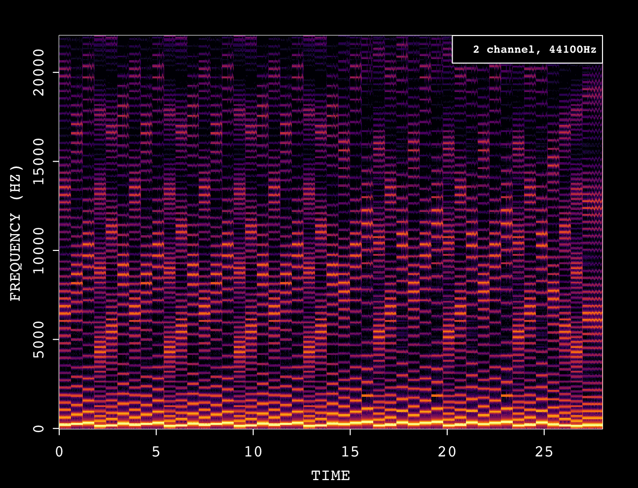
As you can observe from this example, each horizontal line (a.k.a. sequences of dots) corresponds to a sine wave (the lowest is the fundamental, while the rest are the harmonics) and their intensity indicates the amplitude. With this in mind, we can extract the following information:
- Over time, horizontal lines tend to drastically displace. That’s the pitch of the Pulse channel changing.
- The start of each note is loud (the dots are vibrant) followed by a quick quell. That’s the APU’s envelope control in action.
- Moreover, at the end of the decay period, a vertical line shows up. It’s quite brief so it’s not easily audible but, in any case, that’s noise (a short popping sound) and I suspect it’s a deficiency of the APU.
- Holding a note for more than 0.25 seconds makes vibrato emerge (continuous fluctuations in the Y-axis). I’m not sure if that’s intentional (using the sweep function) or an adverse effect of the APU.
Notice how most of these observations are not easily derived by just listening to an audio sample; this is the reason for writing this section.
Plotting the APU
To study the NES’ APU, I’ve compiled five spectrograms, each corresponding to one of the APU’s channels, using the previous examples. Alongside them, you’ll find my attempt at unravelling what the data is exhibiting.
Before we start, I must confess that, to gather the data without inaccuracies (such as extra noise), some compromises were made. The recordings were obtained using a Windows program called ‘towave’, which uses band-limited synthesis to solve a fundamental problem with the emulation of PSG-based audio chips. Essentially, pulses, triangles and sawtooths consist of infinite harmonics. However, this doesn’t mix well with modern sound cards which are limited to 44.1 kHz samples. Thus, a technique called ‘band-limited synthesis’ is employed to select the right harmonics within the sound card’s limitations. All in all, this technique provides a feasible balance between performance, accuracy, and aliasing prevention. However, the data may not be 100% identical to its analogue counterpart (which, by contrast, would also introduce other issues, like noise from the recording equipment), but I believe it is to an acceptable degree and, most importantly, does the job for this section of the article.
That being said, let’s get on with the analysis.
Pulse

The theory says that a pulse tone only contains odd harmonics. In other words, the fundamental is combined with its third harmonic, fifth and so forth. Moreover, each harmonic decreases its amplitude the further it is from the fundamental. The amplitude formula is amplitude = 1 ÷ harmonic number [50].
Hence, notice how the intensity of each harmonic on the spectrogram dims the higher it is on the Y-axis. However, the APU’s pulse waves also seem to exhibit the aforementioned vibrato effect which intensifies at each harmonic number. Moreover, areas of the spectrogram that should be empty of any sound contain hushed overtones (possibly the result of noise and other imperfections).
Triangle
A triangle wave is also made of odd harmonics, but their amplitude decreases more rapidly (following the formula amplitude = 1 ÷ harmonic number² [51]).
However, this is not what is shown here. The step-ladder-shaped triangle that the APU produces introduces additional harmonics and increased amplitudes.
Noise
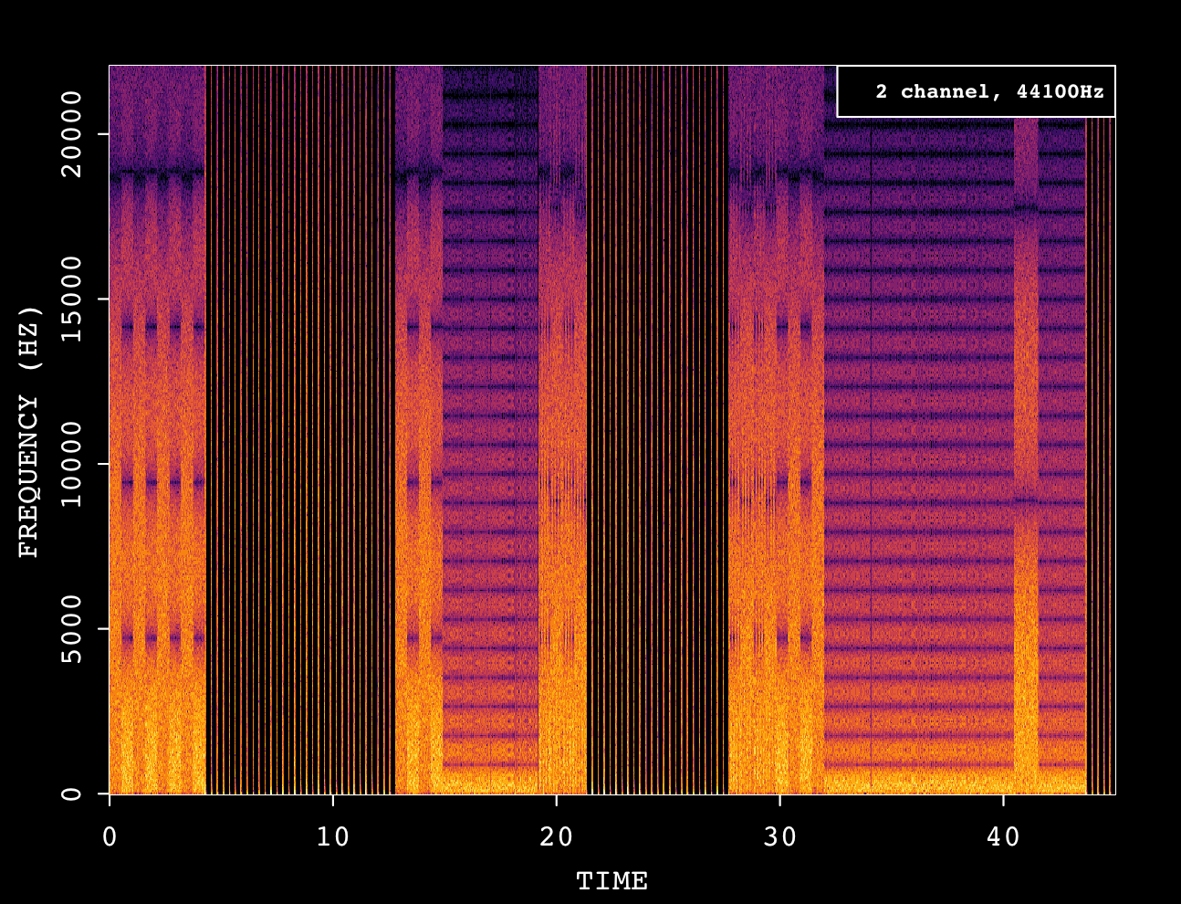
Naturally, noise doesn’t abide by the rules of harmonics and may randomly fill the entire frequency spectrum, hence the absence of a clearly recognisable pitch.
Although, by observing the timeline, you can distinguish between the various noise presets provided by the APU, each exhibiting a unique set of overtones.
Sample
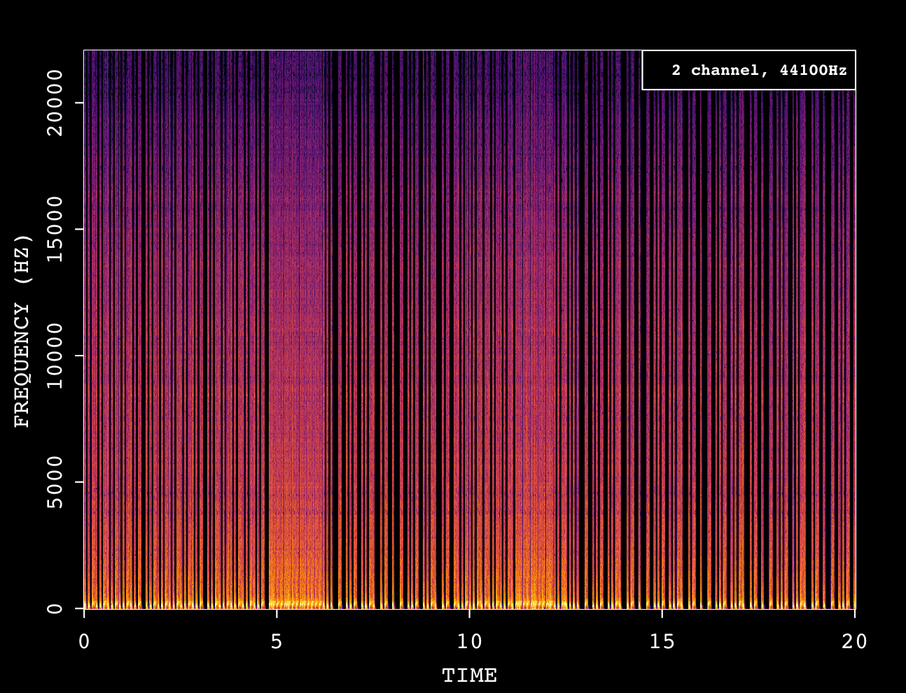
Unlike the previous channels, the sample channel only plays back whatever low-resolution recording the developer feeds to the APU. Considering the example played a drum kit, I can’t see any identifiable traits on the spectrogram (apart from similarities to white noise).
Sawtooth

As a bonus, let’s also check out the Sawtooth channel from the VRC6 expansion. To begin with, a perfect Sawtooth wave is made of all the harmonics and each exhibits decreasing amplitudes (where amplitude = 1 ÷ harmonic number [52]).
This is quite a requirement for digital equipment and is naturally unaffordable for a game cartridge (which may not even need such perfection!). So, similarly to the APU’s triangle waves, the VRC6 sequences Sawtooth waves in 7 cycles (and thus produces similar step-ladder effects).
Consequently, the respective spectrogram appears very cluttered, as the VRC6’s approximation techniques fill the wave with extra harmonics in various places.
Conclusion
Well, it seems that the NES’ synthetic waveforms are nowhere near shaped as the theory dictates. Does this mean the APU is flawed? Not at all! The design of the APU ultimately gave this console its unique and identifiable sounds - these characteristics, whether intentional or not, made the spectrograms display unusual patterns.
As a side note, while perfect geometry may be visually appealing, our ears are surprisingly less receptive to waveforms with excellent edges! (you may start hearing popping noises).
Looking ahead, sound analysis using spectrograms will prove useful in other articles, whether for simple analysis or for comparing different systems. However, it is important to note that these graphs are not the mother lode tool by all means, especially with sound samples that have been mixed with too many channels or instruments, which can complicate their decomposition. Nevertheless, they provide a solid foundation for any kind of objective study.
Games
NES games are mainly written in the 6502 assembly language and reside in the Program ROM, while the game’s graphics (tiles) are stored in Character memory.
Furthermore, games were sold (or rented out) at retail stores under the approval of Nintendo.
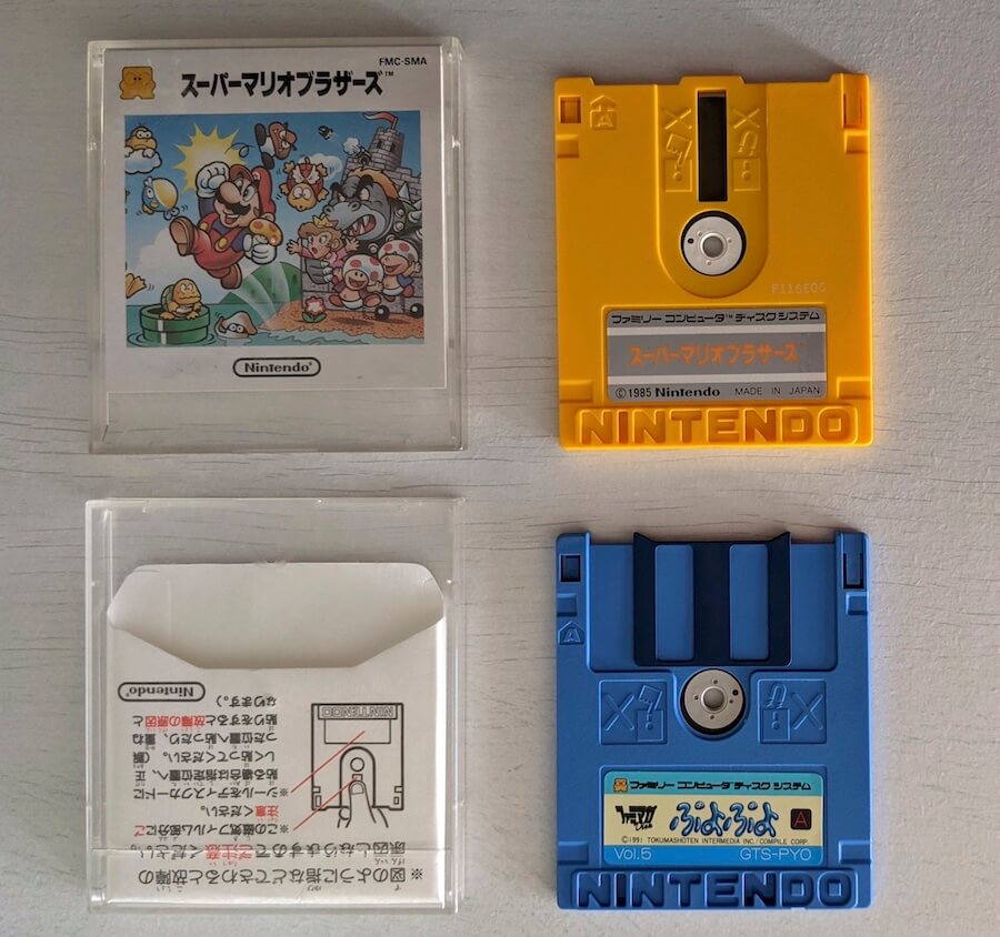
The alternative medium
Even though it was only released in Japan, I thought this would be a good opportunity to introduce a short-lived but peculiar add-on that, just like the mappers, brought in more capabilities to this console. This peripheral, called the Famicom Disk System (FDS), shipped in 1986 (~3 years after the Famicom). It resembled an external floppy drive and came bundled with an oddly shaped cartridge called the ‘RAM adapter’.


The Famicom Disk System added the following functionality to the console:
- A new medium of distribution for games called Famicom Disk [55]. Based on the ‘Quick Disk’ by Mitsumi, it offers ~64 KB of data per side and is re-writable.
- An extra audio channel that uses wavetable synthesis [56].

Unlike multi-chip cartridges, the floppy is a simple medium. Hence, all game data needs to be squashed inside, though it is organised with the use of a proprietary file system.
Nonetheless, the architecture of the Famicom/NES strictly enforces segregated Program and Character memory. The ‘RAM adapter’, which came with the box, addresses this by housing 32 KB of Program RAM and 8 KB of Character RAM to buffer the game data read from the floppy disk. In doing so, this setup enables the console to read data as if it were reading from a cartridge-based game.
To operate the drive, the RAM adapter embeds an additional 8 KB ROM to store a Basic Input/Output System (BIOS) [58]. This program performs the following tasks:
- Displays a splash animation.
- Bootstraps the game from the floppy disk. Behind the scenes, the BIOS contains routines to copy the floppy’s contents to the appropriate memory chip, allowing the console to read them.
- Provides I/O APIs for games to use, such as traversing the disk’s file system.
During that era, Nintendo deployed some ‘kiosks’ at retail stores, so users could bring their floppies and overwrite them with a new game at a reduced price.
Unfortunately, after a few years of lifespan, the Famicom Disk System was discontinued. Consequently, subsequent games reverted to the cartridge medium. On the bright side, new mappers were introduced with similar (or better) capabilities compared to the FDS’ functions.
Anti-piracy and region lock
Nintendo was able to block unauthorised publishing by including a proprietary lockout chip called the Checking Integrated Circuit (CIC) [59]. It is located on the console’s motherboard and connected to the reset signal, making it difficult to remove.
The CIC runs 10NES, an internal program that verifies the presence of another lockout chip in the game cartridge. If the verification fails, the console enters an infinite reset loop.
Both lockout chips are in constant communication during the console’s uptime. Nonetheless, this system can be bypassed by cutting one of the pins on the console’s lockout chip, which places it in an idle state. Alternatively, sending a -5V signal can halt it.
The CIC exists in response to the video game crash of 1983. Nintendo’s then-president, Hiroshi Yamauchi, decided that to ensure high-quality games, the company would take responsibility for approving every single title [60].
You’ll notice that the Japanese model of the console, the Famicom, was released before the 1983 crash. That’s why neither game cartridges nor the console includes CIC circuitry [61]. Instead, the pins are used for optional sound expansion.