Supporting imagery
Models
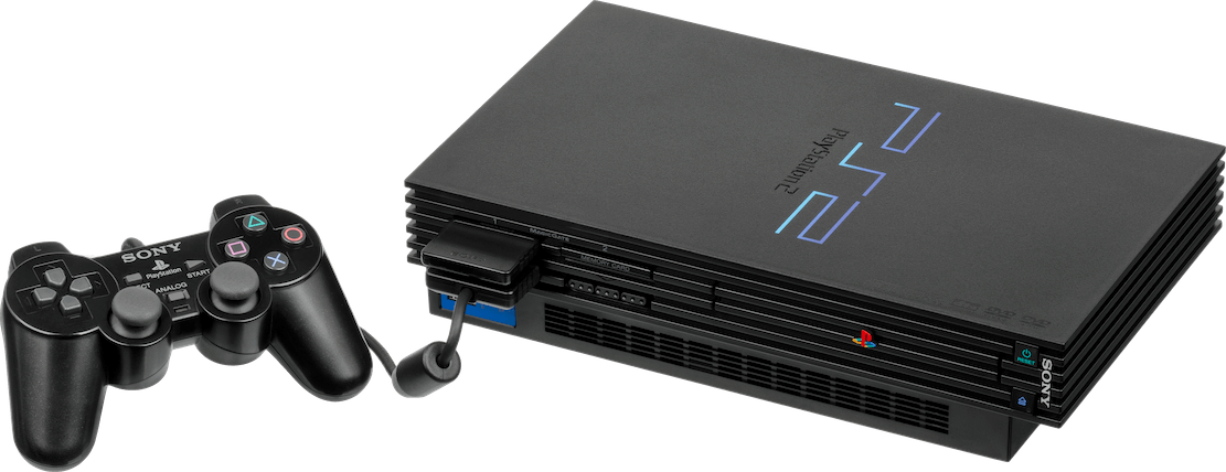
Released on 04/03/2000 in Japan, 26/10/2000 in America and 24/11/2000 in Europe
Motherboard
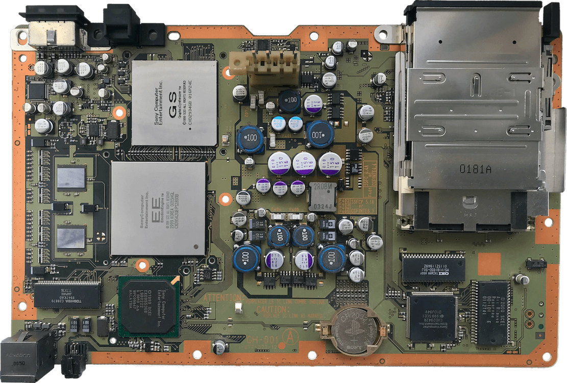
Showing revision 'GH-001' from model SCPH-10000 only released in Japan.
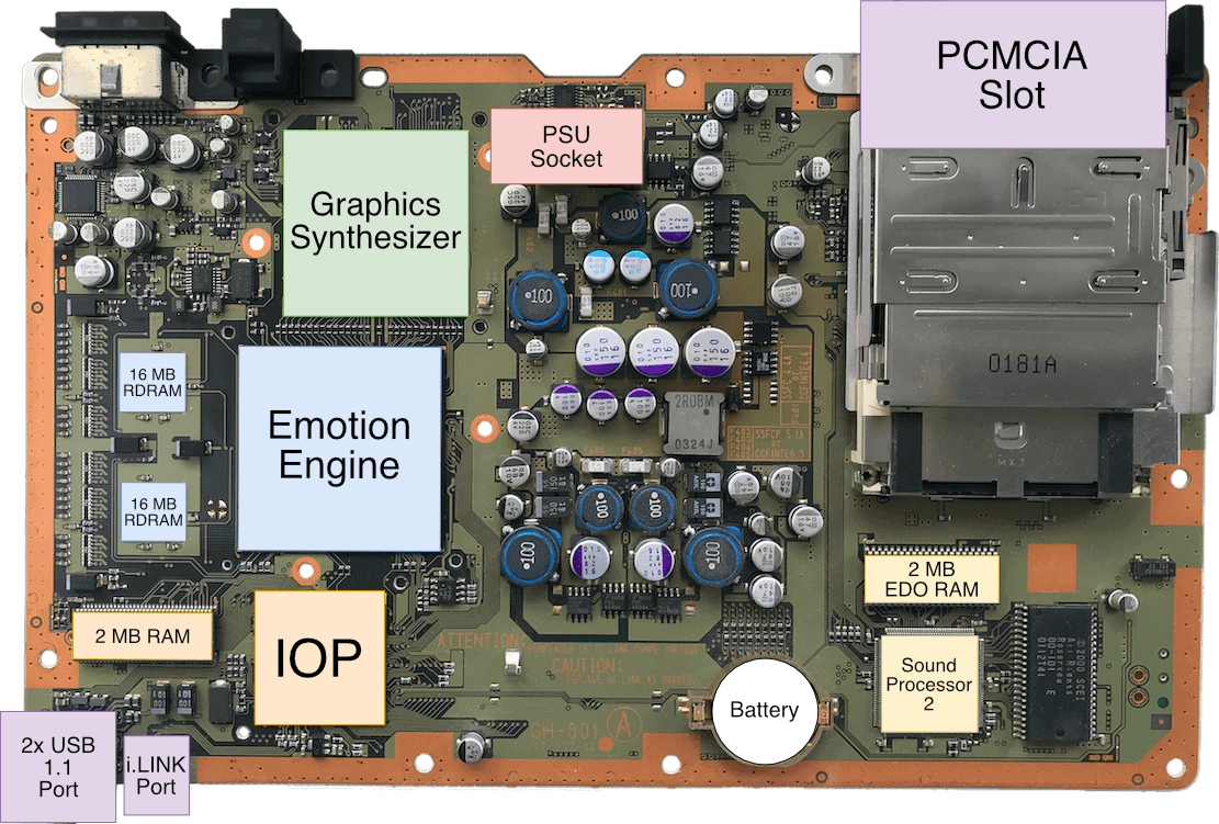
Thanks to the donations received, I was able to purchase this model and take a proper photo to allow me to identify most of the chips.
I presume the chip at the bottom right corner is the 4 MB BIOS ROM
Diagram
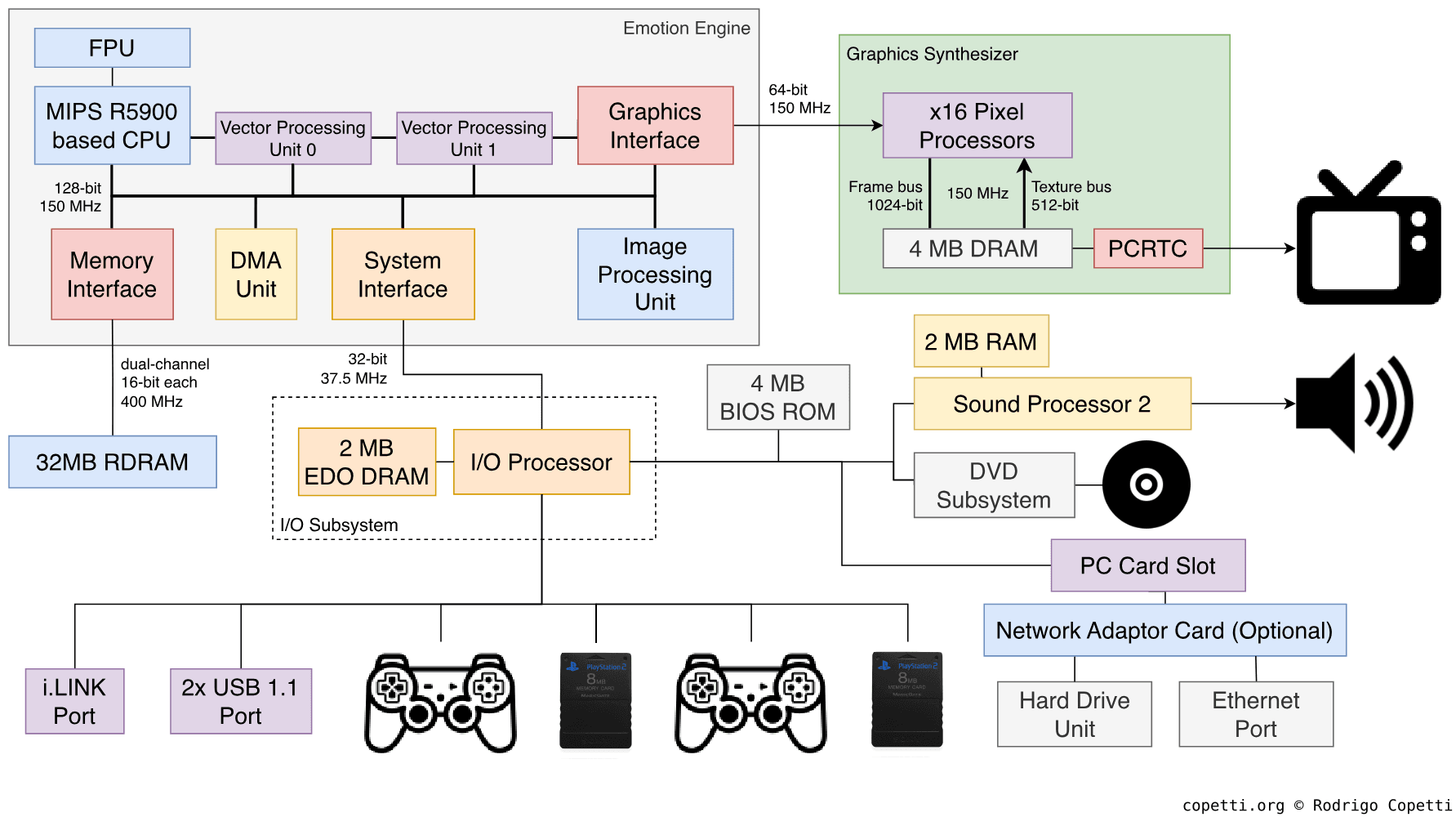
The original design (Implemented on revision 'SCPH-10000').
Each data bus is labelled with its width and speed.
This architecture went through many revisions, more details below
A quick introduction
The PlayStation 2 was not one of the most powerful consoles of its generation, yet it managed to achieve a level of popularity that was unthinkable for other companies.
This machine is nowhere near as simple as the original PlayStation, but we will see why it didn’t share the same fate as previous complicated consoles.
CPU
At the heart of this console, we find a powerful package called Emotion Engine (EE), a joint project by Toshiba and Sony [1] running at ~294.91 MHz [2].
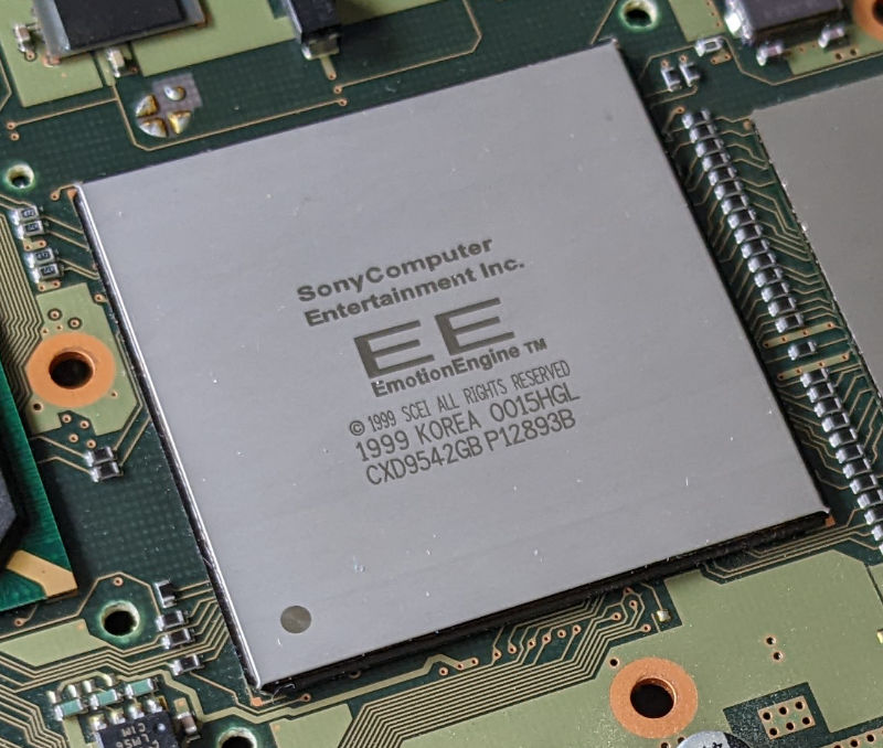
This chipset contains numerous components, one of them being the main CPU. The rest are at the CPU’s disposal to speed up certain tasks. For this analysis, we’ll divide the EE into three sections:
- The leader: The main component that controls the entire chip.
- The memory available, a crucial ingredient that enables the processors to do meaningful operations.
- The co-processors: These accelerate particular computations.
The leader
In a nutshell, the main CPU is a MIPS R5900, an exclusive MIPS core designed for this console. You may recall how Sony started venturing into MIPS silicon with the very first PlayStation (where we can find a MIPS R3000A second-sourced from LSI). For the next generation, we’ve got a MIPS ‘R5900’… but what does that name mean for us?
To understand what’s hidden behind these new numbers, let’s take a look at some history surrounding that era.
Outperforming success
The MIPS R4000 was a popular CPU series adopted by a wide range of systems, including a close competitor. Thanks to its success, MIPS brought a once-unaffordable range of advancements (64-bit computing, 8-stage pipelines, and so forth) to the masses.
Fast forward, the next big leap arrived in 1995, with the release of the R10000. Now under the funding of SGI, MIPS produced a new processor that took the R4000’s parallelism capabilities miles further, debuting techniques like [3]:
- Speculative execution: The CPU predicts the result of conditional branches before they are computed. These predictions are based on previous results stored in an internal 512-entry table. Once the condition is computed, if the prediction turns out to be correct, the CPU has saved valuable time. Otherwise, the extra computations are discarded.
- Thanks to this, MIPS finally turned a recurring problem (control hazards) into an advantage.
- In other CPUs, you may find similar functionality referred to as dynamic branch prediction.
- 4-issue superscalar pipeline: Building on the pipelined design, the CPU could now fetch up to four instructions at the start of the pipeline, and distribute them across separate units, allowing the CPU to execute these instructions at the same time. In doing so, the CPU achieved a greater degree of parallelism.
- Out-of-order execution: The CPU could also re-arrange the sequence of instructions to keep its units as busy as possible… as long as doing so didn’t introduce any hazards.
- L2 cache with a 128-bit bus, enabling to pull more data into the CPU at a time, which was becoming a necessity given the previous enhancements.
Such innovation came at the cost of a complex design, however, and the final product was anything but cheap. SGI only bundled it with high-end equipment, and any attempt to bring it to a home console was out of the question.
High-end for the masses
Even before it reached the market, MIPS was already aware of the commercial limitations of the R10000. So, they hired Quantum Effect Devices (QED) to develop an affordable version of the R10000 for the mid- to low-end market.
As a company founded by former MIPS employees, QED was in the business of designing variants of MIPS cores for the budget sector. They had previously engineered the R4600 Orion, a cut-back version of the R4000, in a similar fashion to the VR4300 (found in the Nintendo 64). Orion was also tailored for Windows NT workstations [4].
In the end, QED came back with a new core called the R5000. It was a continuation of Orion, but was marketed as a cheaper alternative to the R10000, with significant cutbacks [5]:
- In-order execution.
- No speculative execution.
- Superscalar capabilities limited to two instructions (2-issue), with no parallel integer instructions. However, floating-point instructions can still be paired with others.
- As a consequence of the previous choice, L2 cache uses a 64-bit bus instead.
Consequently, this became an ideal CPU for powering modest equipment, such as SGI’s low-end workstations. In any case, notice that the cut-down pipeline could still perform concurrent floating-point operations, as if QED had planned to keep the CPU as an attractive product for vector/3D applications. You’ll soon see that another company quickly took note of that, as well.
As a side note, it’s curious to observe that, on the other side of the pond, there were similar advancements in the opposite direction: ARM joined forces with DEC in the pursuit of lifting ARM chips into the high-end market.
Now that we’ve seen the state of the industry, let’s turn to Sony’s partners.
A special order for Sony
Toshiba had been a MIPS and QED licensee for some time [6] [7], and was no stranger to commercialising MIPS packages. The company was also manufacturing their own MIPS-compatible core, called TX39 [8] [9], derived from the MIPS R3000 [10]. At one point, Sony and Toshiba joined forces to produce a CPU exclusively tailored to Sony’s upcoming console.
This was a tremendous benefit for Toshiba: very often CPUs are required to fulfil a wide range of requirements from different stakeholders, and in doing so it constrains opportunities for specialisation. Now, there was only a single purpose: 3D gaming. Thus, leaving plenty of room for all kinds of innovation.
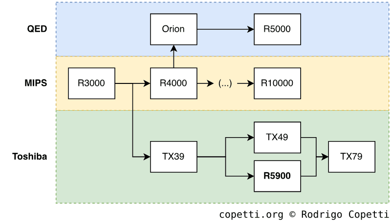
That being said, Toshiba ended up grabbing their TX39 design and combining it with ideas from their upcoming TX49 core, the R5000, and vector accelerators. The new core was called R5900 and introduced the following ‘3D’ enhancements [11]:
- A variation of the MIPS III ISA. This includes the original 64-bit ISA previously seen on the Nintendo 64, but extended with interesting opcodes. Sony added some instructions from MIPS IV (prefetch and conditional move), along with their own SIMD extension - called multimedia instructions - to accelerate vector calculations (similar to the SH-4, but integer-only).
- The multimedia instructions are still 32 bits wide, but can operate up to three 128-bit vectors at a time. They offer operations such as vector arithmetic, min/max, and many kinds of scalar combinations for forming new vectors.
- 32 128-bit general-purpose registers: Another significant Toshiba-branded enhancement. Forget about the typical 32-bit storage; we’ve stepped into the 128-bit realm now. Nevertheless, the majority of operations will hardly use all the available space (MIPS words are still 64-bit long). This is where the aforementioned multimedia extension comes into play, as its instruction set makes full utilisation of the extended register file.
- When using the new instructions, each register can store vectors made up of many types of scalars (from two 64-bit integers to sixteen 8-bit ones).
- To prevent performance penalties, these registers are accessed through a 128-bit bus, while the rest of the CPU uses an internal 64-bit data bus.
- Two 64-bit ALUs. Each can operate on 64-bit integers independently, but they can also be combined to form a 128-bit ALU. The latter is the brain behind those shiny multimedia opcodes.
Aside from these, we also find other improvements that developers may welcome as well:
- A 6-stage pipeline: That’s one additional stage compared with the predecessor’s.
- 2-way superscalar execution: Thanks to the two ALUs, up to two 64-bit integer operations are now executed in parallel.
- This restores another advantage of the MIPS R10000.
- 24 KB L1 cache: Divided into 16 KB for instructions and 8 KB for data.
- The circuitry also implements a prefetch function to cache instructions and data before they are requested. This is done by including extra logic that can identify which places in memory are requested more often.
- 16 KB of Scratchpad RAM, also known as ‘Fast RAM’.
- Memory Management Unit (MMU): Interfaces memory access with the rest of the system.
Moreover, the core is complemented by a dedicated Floating-Point Unit (FPU) - identified as ‘COP1’ - that accelerates operations with 32-bit floating-point numbers (also known as floats in C). This is a peculiar block, as it doesn’t follow the IEEE 754 standard, most notably because it lacks support for infinity (which is computed as 0 instead) [12]. Apart from that, it features 32 32-bit registers.
A recognisable memory choice
Next to the Emotion Engine are two blocks of 16 MB of RAM, giving a total of 32 MB of main memory. The type of memory used is Rambus DRAM or ‘RDRAM’ (déjà vu!), which is accessed through a 16-bit bus.
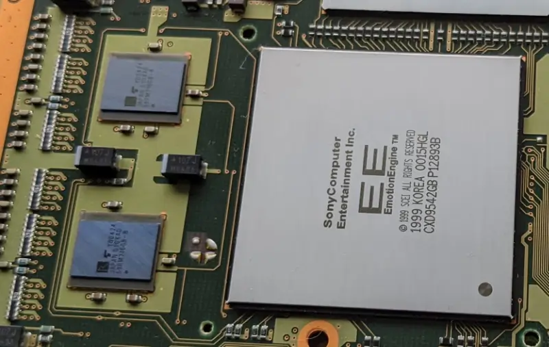
At first, this can be a little disappointing to hear, considering the internal bus of the Emotion Engine is as wide as 128 bits. However, the RAM chips are strategically arranged using a dual-channel architecture, where both chips are connected through two independent 16-bit buses (one bus per chip) to improve data throughput. The resulting setup provides a theoretical 3.2 GB/sec, so rest assured that memory latency is not an issue in this console!
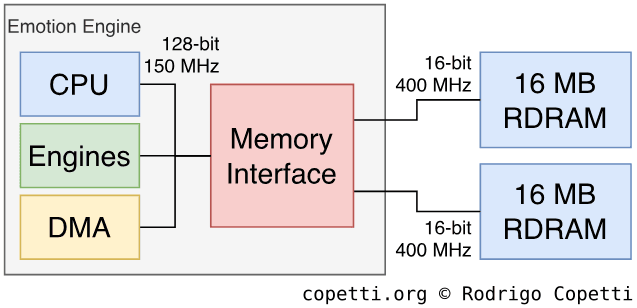
At one corner of the Emotion Engine, there is a powerful Direct Memory Access Controller (DMAC) that transfers data between main memory and Scratchpad, or between main memory and any component inside the EE.
Data transfers are carried out in batches of 128 bits, but here is the interesting part: every eight batches, the main bus is temporarily unlocked. This leaves a small window in which to perform other DMA transfers in parallel (up to ten), or to let the CPU use the main bus. This modus operandi is called slice mode, and is one of the many modes available on this DMA unit. Bear in mind that, while slice mode reduces stalls on the main bus, it does so at the cost of slowing down the overall DMA transfer.
Preventing past mishaps
Whether we want it or not, with the amount of traffic flowing through the Emotion Engine, this design will eventually suffer the consequences of the Unified Memory Architecture or ‘UMA’. That is, multiple independent components trying to access main memory at the same time, causing congestion. Well, to tackle these issues, Sony alleviated the constant demand for memory by:
- Wrapping their processors with lots of cache, thus requiring access to main memory only when absolutely necessary.
- 99% of cache/Scratchpad mentions in this article will be for this reason.
- Adding a 128-byte Write Back Buffer: Very similar to the Write Gather Pipe, but instead of waiting until it’s 25% full, it checks the state of the bus (i.e. congested or free) first.
This sounds very convenient for applications that can benefit from cache, but what about those tasks, such as manipulating Display Lists, which shouldn’t consume cache at all? Luckily, the CPU provides a different memory access mode called UnCached, which only uses the Write Back Buffer. As a result, it won’t waste cycles correcting the cache (product of cache misses).
Furthermore, the UnCached accelerated mode is also available. This one adds a buffer for speeding up the reading of adjacent addresses in memory.
Other interesting bits
Inside the same Emotion Engine package, there is yet another processor called Image Processing Unit or ‘IPU’, this time designed for image decompression. As the successor to the MDEC, the IPU can be useful when a game needs to decode an MPEG2 movie without jamming the main CPU.
Long story short, the game sends compressed image streams to the IPU (hopefully using DMA), which then decodes them into a format that the GPU can display. The PS2’s operating system also relies on the IPU for DVD playback.
Finally, the IPU can also process compressed high-resolution textures, reducing CPU usage and the amount of data that needs to be transferred.
Co CPUs
It’s been two years since the rivals presented their latest offering. If you read the former article and have just started reading this one, I presume you are still waiting for ‘the thing’ that makes the PS2 as powerful as it seemed back then. Now, let me introduce a very important set of components Sony fitted in the Emotion Engine, the Vector Processing Units or ‘VPU’.
Architecture
A Vector Processing Unit is a small independent processor designed to operate on vectors, in particular, vectors made of four floats. These processors are so fast that they spend only one cycle per operation, which can be extremely convenient for geometry processing. Though they exhibit similar unstandardised behaviour to the CPU’s FPU.
Moving on, VPUs are made of the following components:
- Some Vector Unit Memory or ‘VU Mem’: Used as a working space for the Vector Unit. It stores values to be operated and/or the results of previous operations.
- A Vector Unit: The core of the processor. It contains some memory (called Micro Memory) to store a program (called Microprogram) that instructs the unit on how to operate on the data found in ‘VU Mem’.
- The unit implements a 64-bit ISA, and the execution unit is split into two parallel sub-units. The first one multiplies or adds floats, while the other one divides floats or operates on integers. This enables to process both floats and integers concurrently.
- A Vector Interface: Automatically decompresses vertex data coming from main memory in a format that the Vector unit can understand. The interface can also transfer microprograms to Micro Memory.
Functionality
To start working, the vector unit needs to be ‘kickstarted’. For this, the main CPU is in charge of supplying the microcode.
There are two VPUs fitted in the Emotion Engine, but they are arranged differently, giving way to different uses and optimisations.
Vector Processing Unit 0
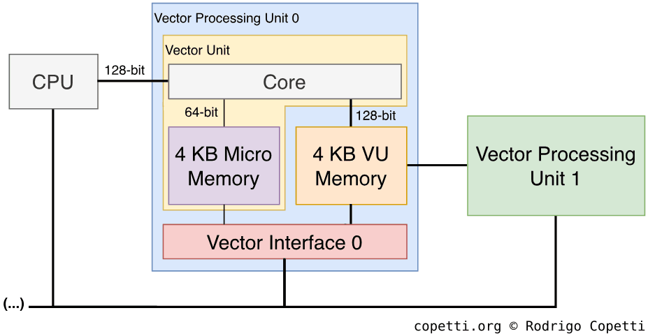
The first VPU, the VPU0, is positioned between the CPU and the other vector unit (VPU1). It serves as an ‘assistant’ to the main CPU.
The VPU0 has two modes of operation:
- Micromode: This is the ‘traditional’ mode. The VPU independently executes ‘microinstructions’ from a microprogram stored in Micro Memory.
- Macromode: The VPU0 becomes the ‘COP2’ of the main CPU and executes ‘macro-instructions’ received from the main CPU through a dedicated 128-bit bus.
- Macro-instructions provide the same functionality as microinstructions, but use different opcodes. Nonetheless, the VPU’s execution unit is no longer split (meaning it can only execute one instruction at a time).
- While this mode doesn’t make full utilisation of all the components of the VPU0, it still speeds up the CPU’s vector operations. Moreover, in terms of development, a co-processor is easier to program than an independent unit (something PC programmers will find helpful).
The VPU0’s memory map also has access to some of the other VPU’s registers and flags, presumably to check its state or quickly read the results of some operations done by it.
Vector Processing Unit 1
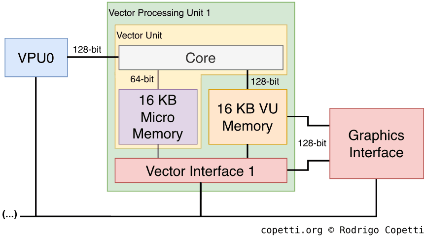
The second VPU found, the VPU1, is an enhanced version of the VPU0, with quadruple the amount of Micro Memory and VU memory. Moreover, this unit includes an additional component called Elementary Function Unit (EFU), which speeds up the execution of exponential and trigonometric functions.
The VPU1 is located between the VPU0 and the Graphics Interface (the ‘gate’ to the GPU), so it includes additional buses to feed geometry to the GPU as quickly as possible (and without requiring the main bus).
On the other hand, and due to its location, the VPU1 only operates in Micromode.
It’s obvious that this VPU was designed for trigonometric operations and may serve as a pre-processor for the GPU. Hence, it’s often put in charge of delivering the well-known Display Lists.
Infinite worlds
A useful model that can be exploited with these units is procedural generation. In other words, instead of building the scene using hard-coded geometry, let the VPUs generate it using algorithms. In this case, the VPU computes mathematical functions to produce geometry data (i.e. triangles, lines, quadrangles, etc.), which is then interpreted by the GPU and ultimately used to draw the scene.
Compared with using explicit data, procedural content is well suited to parallelised tasks: it frees up bandwidth, requires very little storage, and is dynamic (programmers adjust parameters to achieve different results) [13]. Many areas can highly benefit from this technique:
- Complex surfaces (e.g. spheres and wheels).
- World rendering (e.g. terrains, particles, trees).
- Bézier curves, a very popular type of equation in computer graphics used to draw curves. These are turned into a Bézier patch (explicit geometry) and support different degrees of precision based on the level of detail required.
On the other side, procedural content may struggle with animations and, if the algorithm is too complex, the VPUs might not generate the geometry in time.
To sum up, procedural rendering is not a novel technique, but thanks to the VPUs, it opens the door to further optimisation and richer graphics. Nonetheless, its implementation is not simple and Sony R&D published various papers describing different approaches for use on their console [14].
You define the workflow
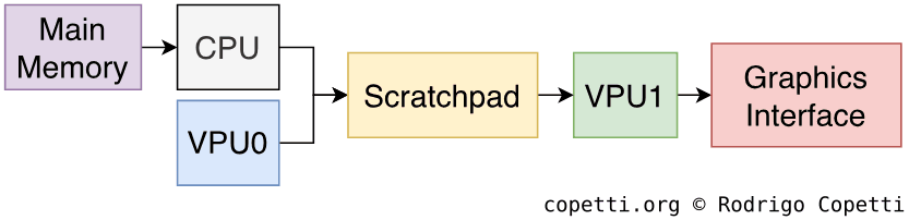
With these new additions, programmers now have plenty of flexibility when designing their graphics engines. To assist with this, Sony devoted additional resources to devising and documenting efficient pipeline designs. The following are examples of graphics pipelines optimised for different types of workloads [15]:
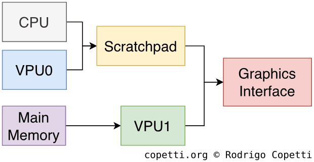
In the first example, the Parallel design, the CPU is combined with the VPU0 in Macromode to produce geometry in parallel with the VPU1. The CPU/VPU0 group makes full use of Scratchpad and cache to avoid using the main bus, which the VPU1 relies on to fetch data from main memory. In the end, both rendering groups concurrently send their respective Display Lists to the GPU.
The second example, the Serial design, proposes a different approach, with the CPU/VPU0 group working as a preprocessor for the VPU1. The first stage fetches and processes all the geometry that the VPU1 subsequently turns into Display Lists.
So far, these have been examples from a theoretical point of view, but to explain a more ‘practical’ implementation, I’m going to refer to a video Jon Burton published regarding the development of one of their PS2 games [16].
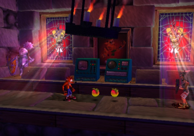
The former director of Traveller’s Tales explained how his team achieved a particle system fully encapsulated within the VPU1. In a nutshell, the VPU1 focused on reading a pre-populated database from its VU memory. This enabled to calculate the coordinates of particles at any given time, without depending on any other component. Finally, the processed data was transformed into Display Lists and sent straight away.
With this approach, the CPU was significantly offloaded, allowing it to carry out other tasks like AI and physics.
There are many more examples out there, but to sum things up: it is now up to the programmer to find the optimal setup, and that is a good thing.
Graphics
Considering all the work done by the Emotion Engine, is there anything left? The last step, actually: Display!
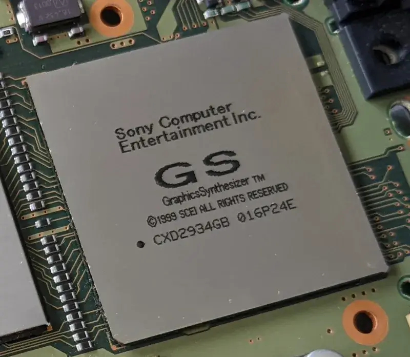
There’s a simple but speedy chip specialised in this: the Graphics Synthesizer (GS) running at ~147.46 MHz [17]. It contains 4 MB of DRAM embedded within it to do all processing in-house, thus removing the need to access the main memory. The embedded Dynamic RAM (eDRAM) is connected via separate buses based on the type of data needed.
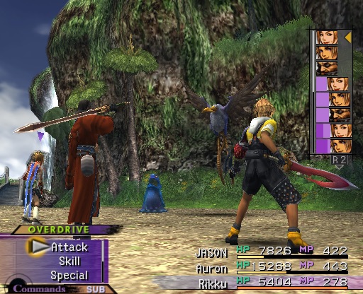
The GS has fewer features than other graphics systems previously reviewed in this series. Nonetheless, it’s very fast at what it does.
Architecture and design
This GPU only handles rasterisation and that is… generating pixels, mapping textures, applying lighting, and other effects. This means there are no vertex transformations (these are covered by the VPUs). Also, this is a fixed-function pipeline, so no fancy tweaking or shaders either: you are stuck with a fixed shading model (e.g. Gouraud).
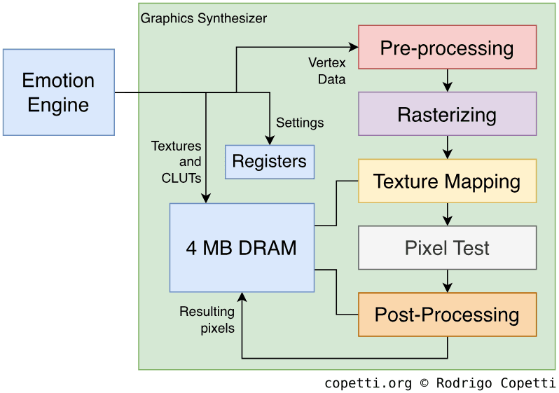
It looks pretty simple, right? Well, let’s dive deeper to see what happens at each stage.
Pre-Processing
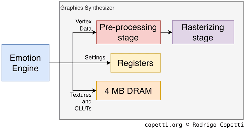
The Emotion Engine kick-starts the Graphics Synthesizer by filling its embedded DRAM with the required materials (Texture bitmaps and Colour Lookup Tables, the latter also known as ‘CLUTs’), assigning values to the GS’s registers to configure it, and finally issuing drawing commands (Display Lists) that instruct the GS to draw primitives (points, lines, triangles, sprites, etc.) at specific locations on the screen.
Additionally, the GS preprocesses some values that will be needed for later calculations. Most notably, it calculates the Digital Differential Algorithm value, which will be used for interpolation during drawing.
Rasterisation
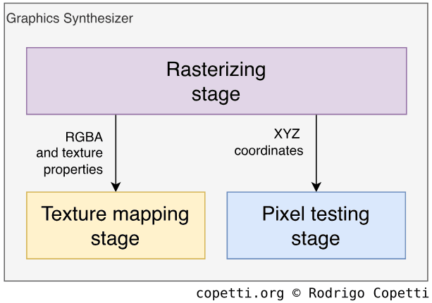
Using the values calculated previously, the rasteriser generates pixels from the primitives [18]. This unit can concurrently generate 8 pixels with textures, or 16 pixels without. Each processed pixel carries the following values:
- RGBA: Corresponds to the gradient of Red, Green, Blue, and Alpha (transparency).
- Z-value: Used for depth testing in later stages.
- Fog: Optional, to simulate fog in the environment.
- Texture properties: Contains the address of the texture in DRAM and other properties (coordinates, level of detail, filter, etc.) that will be used in the next stage.
The rasteriser also performs Scissoring Tests to discard polygons outside the frame area (based on their X/Y values). Some pixel properties are forwarded to the ‘Pixel testing’ stage for further checks. Lighting is also provided by selecting one of the two choices available: Gouraud and Flat.
The resulting pack is then delivered to the ‘Texture mapping’ engine, but each property is operated by a specialised ‘sub-engine’, which enables the processing of different properties in parallel.
Texturing
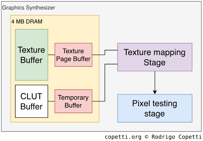
This stage is powered by a large Pixel Unit that can compute up to 16 pixels at a time. Here, textures are mapped onto the polygons (now pixels). Furthermore, fog and anti-aliasing effects can be applied as well.
Texture maps are fetched from DRAM in an area defined as Texture buffer, although this is interfaced by a separate area called Texture Page Buffer, which seems to serve as a caching mechanism for textures. CLUTs are also mapped using this page system. Both elements are retrieved through a 512-bit bus.
The Pixel Unit performs perspective correction to map textures onto the primitives (a significant improvement over the previous affine mapping approach). Moreover, it also provides bilinear and trilinear filtering, with the latter making use of mipmapped textures.
Testing
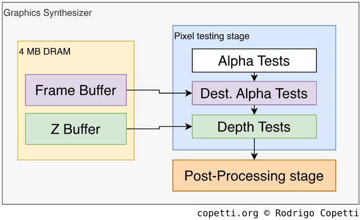
Here, certain pixels are discarded if they don’t meet several requirements, implemented as a series of tests:
- Alpha test: Compares a pixel’s alpha value (transparency) against the ‘standard’ value. This is because, in some cases, the alpha value is required to fall within a certain range or greater/less than an arbitrary value.
- Destination Alpha test: Checks the pixel’s alpha value again before drawing it to the frame buffer.
- Depth Test: Compares the pixel’s Z-value against the corresponding Z-value in the Z-buffer. This avoids processing pixels that would otherwise be hidden behind other pixels.
Post-Processing
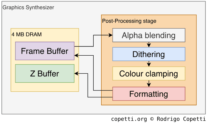
The last stage can apply some effects to our new pixels using the previous frame-buffer stored in local DRAM [19]:
- Alpha Blending: Merges the colours of the current buffer with those of the previous one in memory.
- Dithering: Large RGBA values need to be trimmed, so dithering can be applied to soften the resulting loss of precision.
- Colour Clamping: After applying operations such as Alpha Blending, the new RGB value may exceed the valid range (0-255), so clamping sets the value within that range.
- Formatting: Converts the final frame-buffer generated by the pipeline into a format that can be stored in memory.
Finally, the new frame-buffer, along with the updated Z-buffer, is written to memory using a 1024-bit bus.
Even more post-processing
There’s a dedicated component inside the GS called Programmable CRT Controller or ‘PCRTC’, which reads regions of the frame-buffer stored in memory and sends them through the video output [20], so you can see the frame on a TV. But that’s not all: it also contains a special block called Merge Circuit that allows to alpha-blend two separate frame-buffers (useful if games want to reuse the previous frame to form the new one). The resulting frame can be output through the video signal and/or written back to memory.
Notice how this encoder has ‘CRT’ embedded within its name. Its inherent consequences are discussed at the end of this chapter.
Better models
With all that said, it’s no surprise that game designers refreshed their character models to take advantage of smoother and more detailed surfaces. Take a look at this ‘Before & After’.


 Interactive model available in the modern edition
732 triangles.


 Interactive model available in the modern edition
2226 triangles.
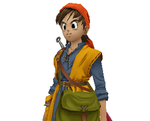
Here are characters from new game series. These were modelled with high levels of detail from the ground up.

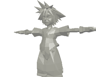
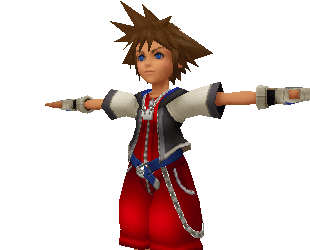 Interactive model available in the modern edition
2744 triangles.

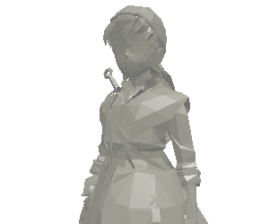
 Interactive model available in the modern edition
2700 triangles.
It’s worth mentioning that games like Dragon Quest implemented a custom lighting model known as Cel Shading (a term I have mentioned before). However, in my previous articles, I explained that the GPU was mainly responsible for this effect. In the PS2’s case, the required colour calculations are presumably performed by the Emotion Engine, since the GS isn’t as flexible as other GPUs.
Video Output
To recap, PCRTC sends the frame buffer through the video output signal. This is transmitted through a multi-purpose AV Multi Out socket, the exact interface found in the PS1.
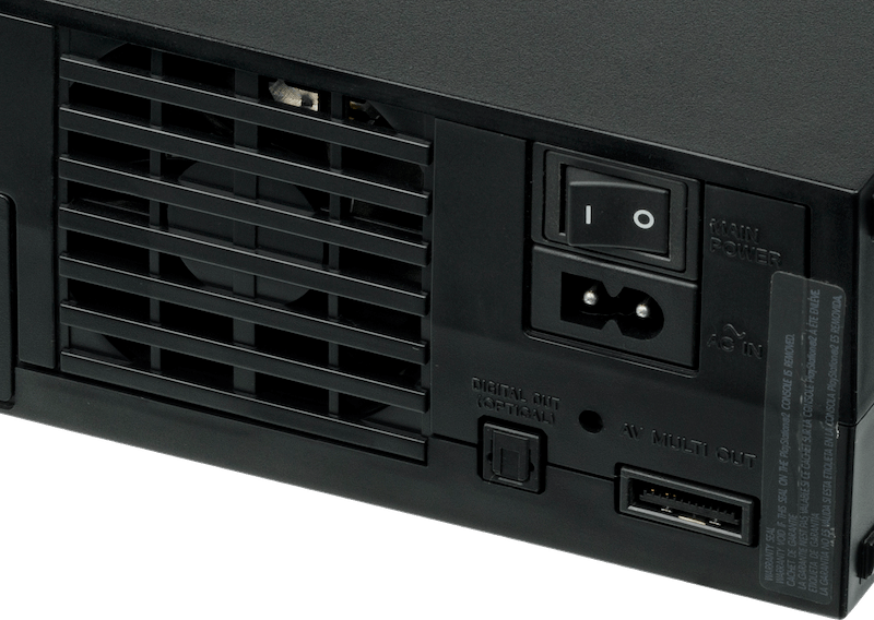
A significant change, however, is that the video encoder can now reuse the RGB pins to transfer a component signal (YCbCr) instead. This is activated by software through the system settings. Apart from the improvement in image quality, this allows PCRTC to output video beyond the standard interlaced PAL and NTSC dimensions.
The common bunch
Speaking of which, PCRTC can broadcast interlaced NTSC (480i), PAL (576i), and progressive NTSC only (480p).
But that’s not all: PCRTC also supports VESA-compliant modes (offering up to 1280 x 1024-pixel resolutions) for use with a VGA adaptor (included with the Linux PS2 kit — I explain more in the ‘Games’ section). Be that as it may, the PS2’s AV Multi Out didn’t add any new pins for VESA, so it outputs the sync signal through the green wire, meaning that not all VGA monitors are compatible.
Ambitious resolutions
PCRTC also has an unusual mode that outputs 1080 interlaced scan-lines (1080i). Does that mean the PS2 can ‘display HD’? Not in the modern/digital sense; it’s far more constrained:
- The PS2 can’t fit a full HD frame into its 4 MB of video memory, but the Graphics Synthesizer supports dynamic frame buffers, allowing a game to render any frame of virtually any size, provided the width is a multiple of 64 pixels. The height can be arbitrary. Games typically rendered frames close to NTSC dimensions to maintain acceptable performance.
- PCRTC operates independently and can crop or scale a frame to fit the chosen output dimensions. Since 1080i is an interlaced format, PCRTC only sends fields containing 540 scan-lines, each with up to 1920 samples.
- Widescreen frame-buffers are also expensive to render and, given their limited adoption, games resorted to anamorphic widescreen when supporting this aspect ratio.
- The European market was still affected by the common-denominator effect: PAL games often used letterboxing to conceal the unused horizontal lines and slowed down the refresh rate to comply with the 50 Hz standard. I call these bad ports.
To put this into practice, 1080i games such as Gran Turismo 4 rendered frames at 576 x 480 pixels, and instructed PCRTC to interlace its image. This effectively produced a 960i signal, which the game called ‘1080i’. You may like to know that Sony was, at the same time, selling premium ‘HD’ Trinitron CRTs that could display the extra scan-lines.
In any case, it’s easy to see why 1080i saw limited adoption. Most game studios were unwilling to accept the performance penalty for a format that had yet to gain widespread popularity. In fact, this brings us to the next topic.
The stretching reality
So far, we’ve looked at the PS2’s exceptional output modes, but what was the typical resolution used by games? The answer is… the small ones.
You see, when the Dreamcast debuted two years before, its GPU focused on unifying aspect ratios (using a common 640 x 480 resolution) and broadcasting full progressive-scan images (480p). These numbers were already part of the VGA protocol (used by computer monitors) and would later be favoured by emerging flat-panel TVs.
This did tax Holly, however. Consequently, when Sony designed the Graphics Synthesizer, the focus shifted towards image detail and frame rate. After all, 4 MB of Video RAM could only do so much.
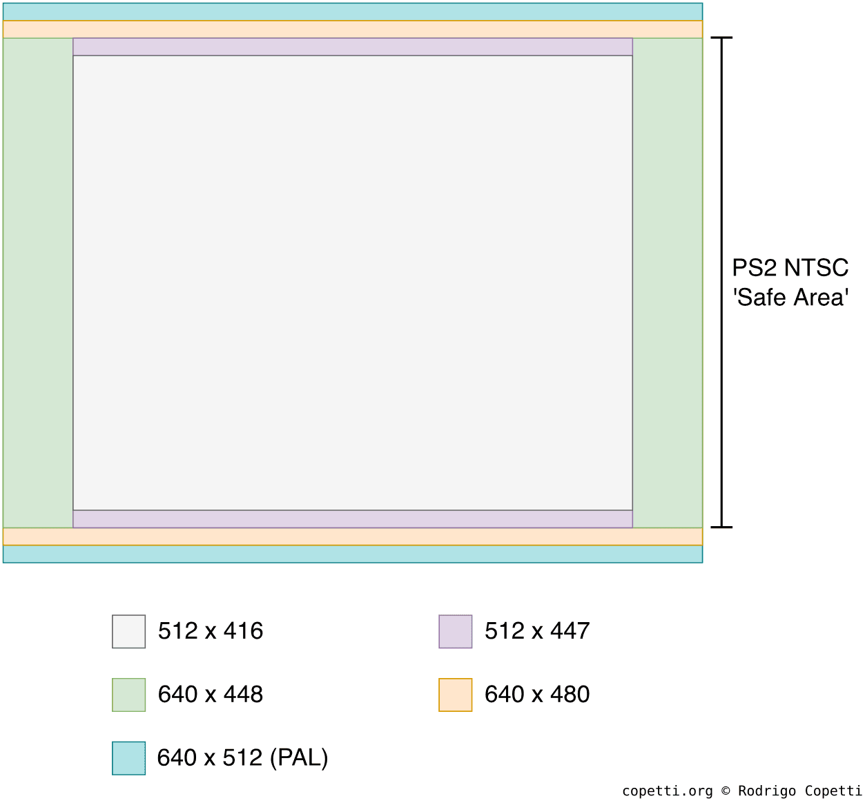
And so, PS2 games exhibited many of the same characteristics as those of the previous generation: varying resolutions, aspect ratios, and amounts of margin. To give you an idea:
- Final Fantasy X renders frames at 512 x 416 pixels.
- Crash Bandicoot: The Wrath of Cortex uses 640 x 448-pixel frames.
- Kingdom Hearts renders at 512 x 447 pixels.
Moreover, all of these games output interlaced video. When this happens, the GS provides two modes: either display the full frame across two fields, or one field per frame.
This trade-off was deemed acceptable because the imperfections of CRT displays helped disguise it. However, once LCD screens became the norm in the late noughties, these shortcomings became increasingly unpleasant. By then, though, Sony was already trying to push the all-digital PlayStation 3 (albeit with an absurd launch price).
Audio
The new audio chip is an incremental update of the original Sound Processing Unit (SPU) called… SPU2! Improvements include 2 MB of internal memory and 48 audio channels, twice the number available on the original SPU.
The SPU2 consists of two internal sound processors, referred to as CORE0 and CORE1, and runs at ~36.86 MHz. Each processor handles 24 channels.
Curiously enough, these are still two independent controllers, and configuring them requires altering their respective registers. However, Sony warned developers that both sets of registers must be updated at least 1/48000 seconds apart. If you hurry too much, the behaviour of the SPU2 becomes unpredictable.
The SPU2 inherits the same effects available on the original SPU. The provided memory serves as a ‘work area’: raw waveform data can be stored there, while additional space can be allocated for processing and applying effects.
Finally, the chip can mix all channels into stereo output. Now, here is the interesting part: the SPU2 can feed the mixed stereo sample back into itself as a new input. This allows the EE to access it (to mix it with additional audio, for instance), or apply further effects, such as reverb, echo, and delay.
Audio out
The audio signal is outputted through two interfaces:
- Digital Audio: Referred to as the Sony/Philips Digital Interface or ‘S/PDIF’, it’s a digital signal that inherently carries less interference.
- Analogue Audio: Passes through the digital-to-analogue converter before reaching the AV Multi Out port. Most TVs are compatible with it.
I/O
When the PlayStation 2 debuted in Japan in 2000, its initial I/O offerings left significant room for improvement. I mean this in the literal sense, as the accessories Sony shipped left plenty of empty space inside the console’s casing. It was only after the international revisions reached American and European shelves, that users realised how this gap would be filled.
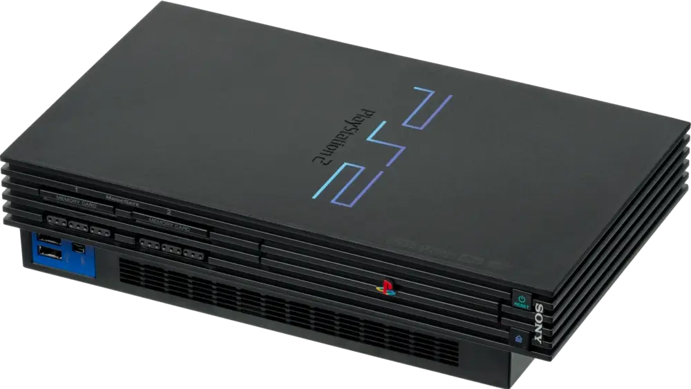
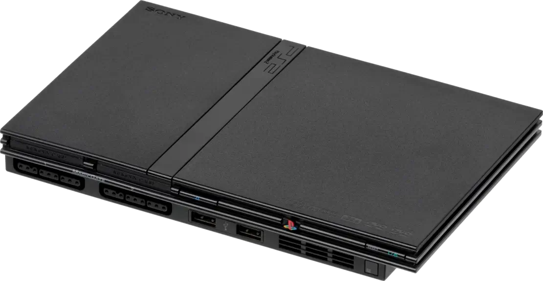
Admittedly, the PS2’s lifespan overlapped with a surge of media-centred interfaces like USB, Ethernet, FireWire, Infrared… some of which were short-lived, whilst others became popular standards.
Sony, as a company, also held a stake in several protocols. Thus, between 2000 and 2013, Sony continuously revisited the console’s design in a way that radically disrupted both its internal and external I/O.
With that in mind, let’s look at what this console offered, from start to finish.
The special CPU
No matter the revision, the PlayStation 2 houses a dedicated processor that arbitrates communication between different components. This separate CPU is called I/O Processor (IOP) and runs at 37.5 MHz, connected to a 32-bit bus [24].
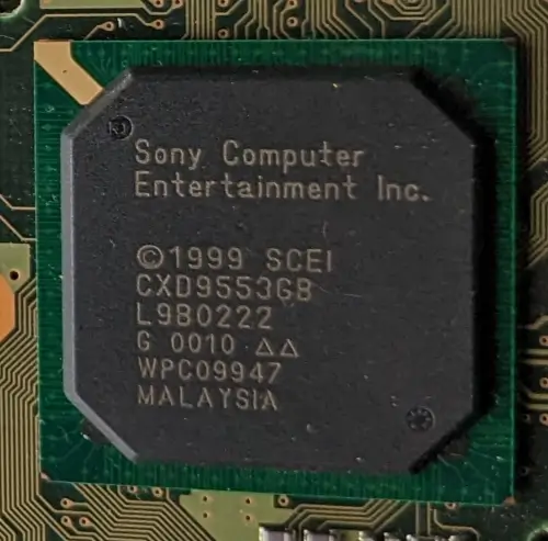
The IOP communicates with the Emotion Engine using a specialised I/O interface called System Interface or ‘SIF’; both endpoints use their DMA units to transfer data between them. All in all, this processor gives access to the front ports, DVD controller, SPU2, the BIOS ROM, and the ‘PC card’ slot.
Initially, the IOP materialised in the form of the original MIPS R3000-based core found in the PlayStation 1, paired with 2 MB of EDO RAM used as a buffer.
The special upgrade
The SCPH-750XX revision (2005), released a year after the ‘Slim’ redesign, swapped the MIPS core for a highly unusual SoC that instead houses [25]:
- A PowerPC 440x5 CPU. This chip is part of the streamlined PowerPC 4xx series spearheaded by IBM and tailored for microcontroller applications.
- An Auxiliary Processing Unit (APU), a package composed of partial MIPS R3000A circuitry (the decoder and ALU), the good-old Geometry Transformation Engine, and extra registers for interprocess communication.
- An Ethernet transceiver, previously distributed as an external accessory.
Sony also fitted 4 MB of SDRAM alongside the SoC (an increase of 2 MB, and synchronous this time).
The new package is referred to as PPC-IOP and runs at a lightning 440 MHz instead. Interestingly, the PPC CPU is still tasked with running MIPS code [26]. This is achieved with the help of a MIPS emulator called DECKARD (stored in the BIOS ROM [27]), which makes use of the additional SDRAM and the APU to accelerate the process.
Given that the inner workings and operating speed of PPC-IOP differ considerably from those of the original IOP, there’s an additional database of patches with entries for each affected game [28]. Furthermore, DECKARD tries to approximate timings using an event handler. However, performance degrades when executing certain instructions [29]. Additionally, almost 24% of SDRAM is left unused for unclear reasons [30].
In light of this, I wonder why Sony redesigned the I/O ecosystem in a way that not only degrades performance but also wastes all its perks. Perhaps this was done solely to reduce manufacturing costs while keeping backwards compatibility (I elaborate more in the following paragraphs). It’s worth mentioning that, at the time, Sony had recently struck a deal with IBM to build the Cell processor as well.
Inherited compatibility
For those PS2 models incorporating the predecessor’s CPU, one can suspect that PS1 compatibility would be part of the package. Conveniently enough, Sony did bundle a PS1 emulator (called PS1DRV) which loads whenever a PS1 disc is inserted. During this process, the IOP is underclocked to operate at PS1 speeds, the EE is ‘repurposed’ to emulate the original GPU, and the SPU2 is remapped to behave like the original SPU.
In PowerPC-based models, PS1DRV runs on top of DECKARD.
External interfaces
At first glance, the console inherited the previous front ports from the original PlayStation, now accompanied by a couple of ‘modern’ interfaces that evolved throughout the years.
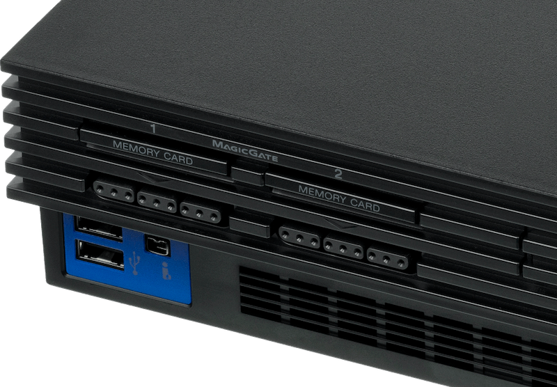
The most popular additions were the two USB 1.1 ports. Their theoretical speed is 12 Mbps, but that’s highly dependent on the IOP’s bandwidth (which tends to be considerably slower). Nevertheless, they remained unchanged across revisions, making them a favoured choice for third-party accessories.
In addition to that, the revision SCPH-500XX (2003) introduced a discreet infrared sensor [32], intended for use with a Sony-branded remote controller (sold separately).
Other interfaces proved short-lived. For instance, until model SCPH-500XX (2003), the console also featured an i.Link port (also known as IEEE 1394, or ‘FireWire’ in Apple’s world). This socket was made for connecting two PS2s for local multiplayer; I presume its utility likely diminished after the ‘Network adaptor’ (explained next) gained popularity.
The unusual combo
On the rear of the console, we also find a slot for PC cards, demonstrating that this console was designed with expandability in mind. To make use of this, you could purchase Sony’s Network Adaptor card, which offered three new interfaces:
- An Ethernet port and a 56k modem port for online multiplayer.
- A proprietary port for an external Hard Disk Drive (HDD) Unit: Also sold by Sony, it packaged a typical 3.5” ATA hard drive with 40 GB of space. The disk enabled games to store temporary data or permanently install themselves there for faster load times. Just a few games leveraged this feature, though, with better adoption in Japan than in the rest of the world.
In later revisions (SCPH-3000X, released the same year), the PCMCIA port was replaced by an Expansion Bay, into which the 3.5” HDD could now be fitted inside the console. Users first had to buy the revised Network Adaptor, which now included an ATA-66 connector on the opposite side.
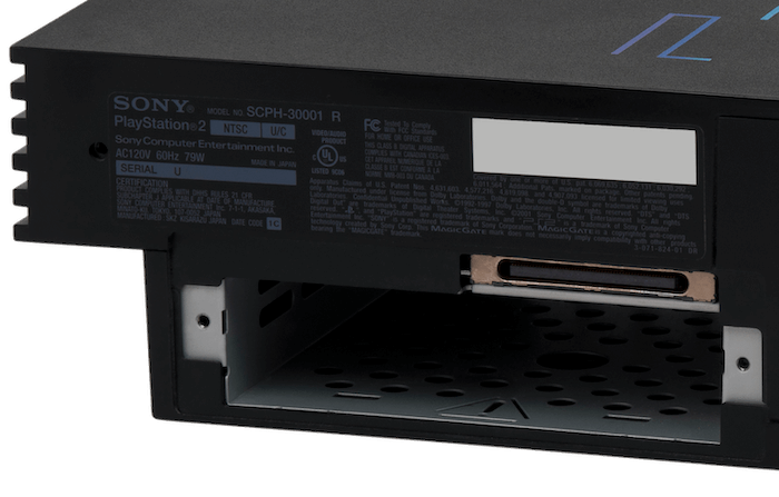
Inside the HDD, data is structured using a file system called ‘PFS’ [34]. Strangely, the layout doesn’t contain a partition table, but rather a primitive catalogue called ‘Aligned Partition Allocation’ (APA). This may be because Sony only shipped 40 GB drives. Hence, scalability wasn’t on their list of priorities.
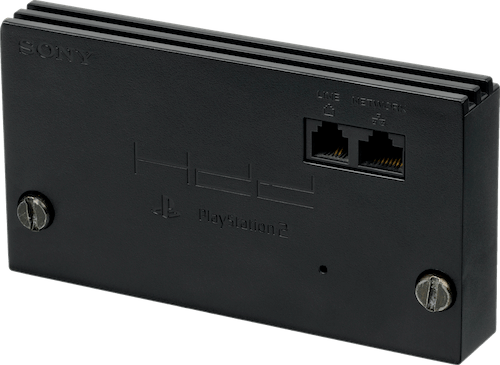
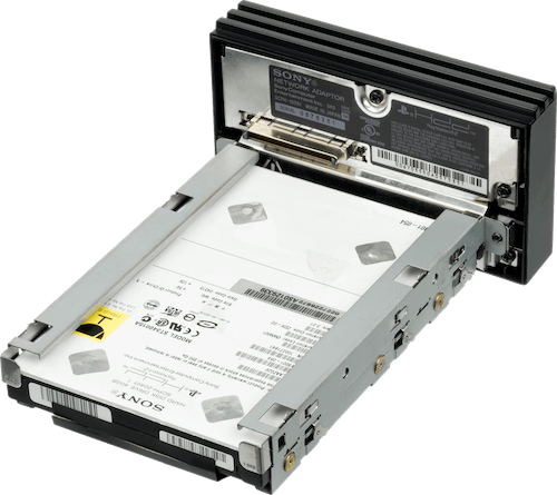
The Ethernet transceiver bundled with the adaptor supports transfer rates of up to 100 Mbps (12.5 MB/s). However, the observed rate is notoriously lower (as low as 2 MB/s in some cases). The explanation is relatively simple: to achieve usable network communication, one is required to implement all the layers of the standard ‘OSI Model’ - and the transceiver is just one piece of the puzzle. The rest is often delegated to the IOP (and therefore handled in software), but due to the IOP’s limited performance [37], this results in a bottleneck.
Slimming down
The major ‘Slim’ revision (2004) not only significantly reduced the console’s size, but also reorganised the entire Ethernet + HDD model: the Expansion Bay was removed, and an Ethernet port was permanently fitted to the rear. Early Slim revisions also bundled a modem.
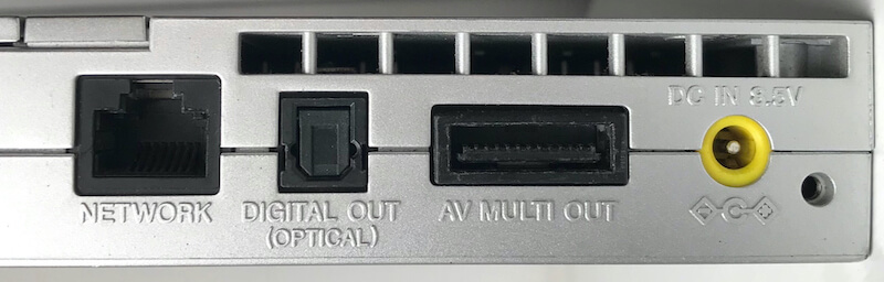
Curiously enough, until 2005, Slim motherboards incorporated the same Ethernet and HDD controller found in the Network Adaptor. It wasn’t until the IOP transitioned to PowerPC that these functions were absorbed into the IOP.
Interactive accessories
Sony’s new controller, the DualShock 2, is a slightly improved version of the PS1’s DualShock. Furthermore, as the standard controller, it unifies all previous DualShock designs into a single variant.
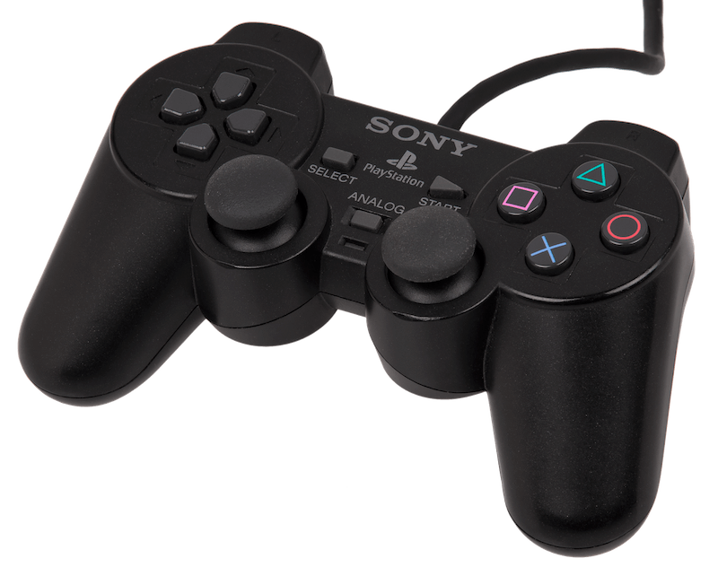
You see, during the days of the original PlayStation, multiple revisions of the original controller were released, each offering distinct features, which also brought fragmentation in the market. Now, for the benefit of developers, there is a single controller that consolidates all previous functionality.
Compared to the original DualShock, the new version retains the two analogue sticks and two vibration motors for richer input and feedback, respectively, whilst introducing pressure-sensitive buttons for a different kind of input.
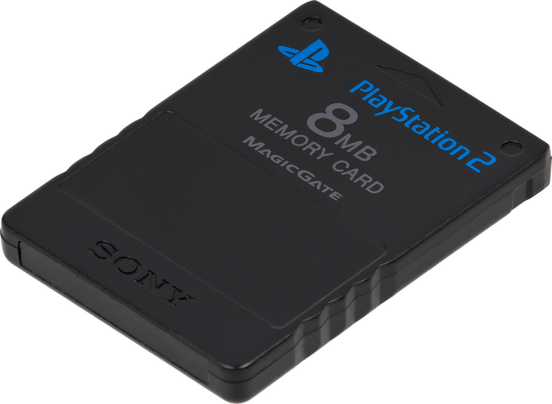
Next to the controller slot is the Memory Card slot, now compatible with PS1 and PS2 protocols. The latter cards embed extra circuitry for security purposes referred to as MagicGate; this is a combination of encryption and authentication that enables games and the OS to restrict data transfers between different memory cards. The IOP takes care of encrypting and decrypting the content, and it does so with the help of the MagicGate chipset (found inside the Memory Card) and the DVD subsystem, which contains the encryption keys.
Some third-party Memory Cards didn’t support MagicGate, however.
The new disc reader
As you may already know, Sony fitted a new type of optical disc drive designed to read two types of discs: CD-ROM XA (for PS1, some PS2 games, and audio CDs) and the new format known as Digital Video Disc or ‘DVD’ (for movies and PS2 games). I discuss further details regarding the DVD medium in the ‘Games’ section.
For now, it’s worth knowing that inside the drive there is a complex subsystem. Building upon the original PlayStation model, the new disc controller is a much more sophisticated piece called Mechanics Controller or ‘MechaCon’ [40]. This circuitry features its own dedicated mask ROM, RAM, EEPROM, and Real-Time Clock (RTC). Aside from managing the drive, it also enforces disc anti-piracy and MagicGate authentication and encryption.
Initially, there was also a separate System Controller or ‘SysCon’ chip that handled power and thermal control throughout the system [41], but with the SCPH-390XX revision (2002), SysCon was absorbed into MechaCon.
As a curious note, the PS2 drive exhibits a longstanding design fault, in which its Digital Signal Processor (DSP) - in charge of processing the signal read - may freeze when the disc is excessively scratched, thereby damaging the laser component [42]. This occurs because the DSP may receive corrupted Error Correction Data (ECC) from the disc and stop functioning, potentially leaving the actuator energised for longer than allowed, causing it to overheat.
Finally, the drive provided maximum read speeds of 48x for CDs (3.69 MB/s) and 4x for DVDs (5.54 MB/s) [43].
Operating System
There’s a 4 MB ROM chip mounted on the motherboard; this stores code for an interactive shell menu and system calls to simplify I/O access [44], which games rely upon.
Upon receiving power, both the MIPS R5900 and the IOP start at address 0xBFC00000 (that’s the signature reset vector for all MIPS CPUs). To handle the dual-processor-same-address conflict, however, the code stored at that address (located at the BIOS ROM) will make each CPU branch to a different location based on its identifier.
In the case of the R5900, our main CPU follows these steps [45]:
- Initialise the hardware.
- Load the Kernel from ROM into RAM. Once loaded, the Kernel provides a layer of abstraction to applications (mostly games) to interact with the hardware. Additionally, it exposes a multi-threading API (cooperative and priority-based).
- The Kernel loads
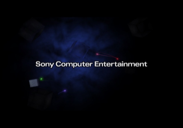
EELOAD, a module that, in turn, bootstrapsOSDSYS. The latter is the program that displays the ‘Sony Computer Entertainment’ splash animation and the shell menu.
Meanwhile, the IOP initialises part of its components and then loads multiple modules; these enable the IOP to access the console’s hardware. Once finished, the IOP enters an ‘awaiting command’ state.
It’s worth pointing out that the use of modules allowed Sony to release new hardware revisions of the PS2 without modifying the IOP’s silicon (until they did), thereby lowering some production costs.
Interactive shell
The functionality of the PS2 shell is pretty much in step with other 6th-generation consoles.
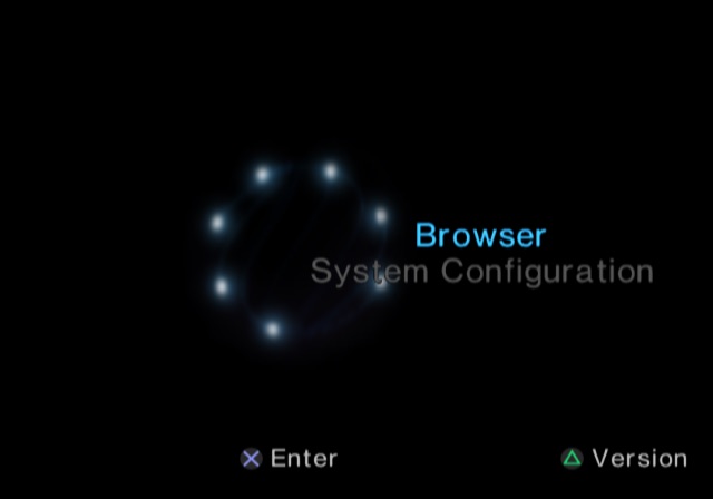
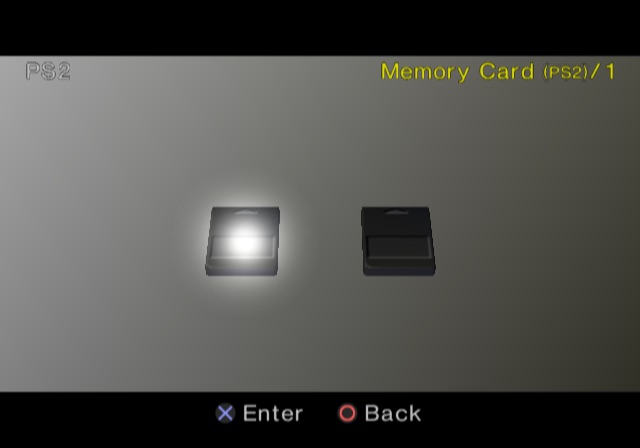
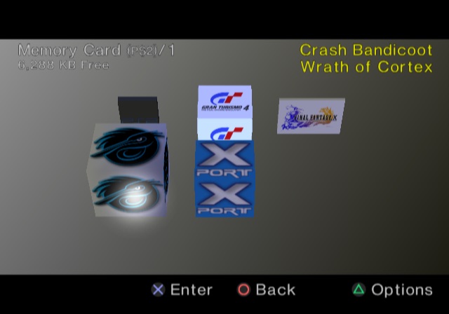
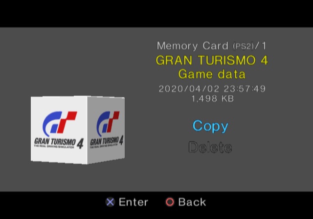
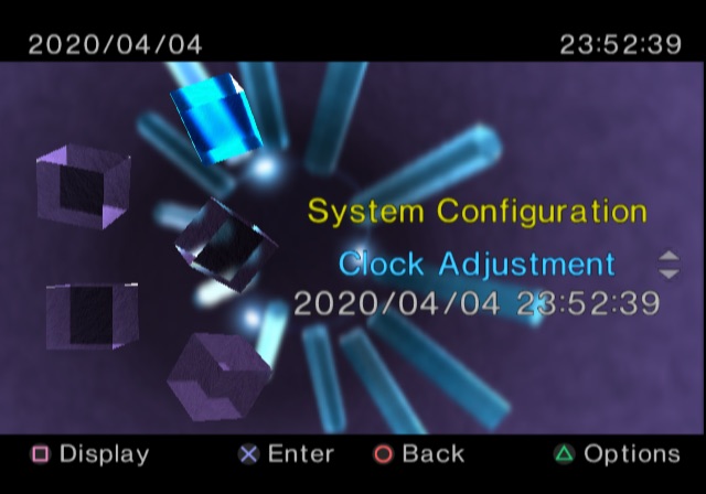
The interface comprises multiple menus for managing typical operations. Some menus even feature 3D visualisations for tasks like organising save data stored on memory cards, whilst others rely on more primitive elements, such as when adjusting the clock. The shell also provides specialised options, such as changing the current video mode.
Updatability
The BIOS is indeed stored in read-only memory, but that did not stop Sony from amending it after the console left the factory. You see, behind the scenes, the BIOS implementation left two doors open for future alterations:
- Applications (games and
OSDSYS) can monkey patch kernel routines at runtime [46]. Both the official SDK and the unofficial ‘ps2sdk’ made extensive use of this, as Sony’s engineers subsequently discovered that the Kernel they shipped was riddled with bugs (pun intended). EELOADsearches an updatedOSDSYSbinary stored on the Memory Card or the HDD [47]. Sony relied on this to add a DVD movie player and HDD support, as neither of these drivers were bundled in the earlier revisions of the console.- These updates were distributed on installation discs that came with the console or the HDD kit (found in the Final Fantasy XI box set).
- Unlike the Kernel, which had to remain backwards compatible with older SDKs, follow-up revisions of the console incorporated previous updates into the BIOS ROM.
- To control distribution, binaries had to be signed with Data Encryption Standard (DES) [48], a symmetric encryption system, with keys only known to Sony (in theory). Additionally, the binaries had to be stored on a device with MagicGate support.
In any case, Sony removed the second method in late PS2 models (with BIOS version 2.30). I presume Sony wasn’t planning any further updates and this merely added attack surface.
Afterthought designs
While the original user interface remained in use throughout the console’s lifetime (and became known worldwide), for a short time, Sony distributed a couple of enhancements.
The first one was HDD-OSD, also called Browser 2.0. It extended the original shell by adding the ability to browse the HDD’s contents, allowing users to list and delete game data stored on the HDD using controls similar to those of the memory card manager. HDD-OSD came packaged on the HDD Utility Disc, which Sony bundled with the PS2 Hard Drive unit.
The second update was more exclusive and extraordinary; it was called PlayStation Broadband Navigator (PSBBN) and reimagined the PS2 experience with a focus on multimedia and online functionality. It was installed as a replacement GUI, introducing new design paradigms based on depth, transparency, and lighting.
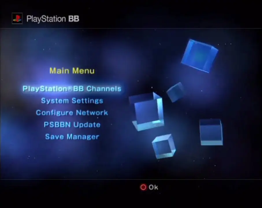
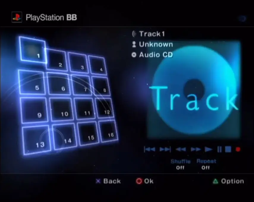
PSBBN was released in 2002, and its UI also featured the concept of Channels, where many multimedia services would be offered:
- Game channels provided online portals by game studios to showcase their content. These also offered downloadable demos.
- The Music channel was an audio player that also allowed to import audio CDs onto the HDD.
- The Photo and Movie channels were used to import and view media from USB storage devices.
In addition to these, there was also a web browser based on NetFront, and a dedicated PS1 emulator called PlayStation One Portable Station (POPS), which could run PS1 games downloaded from a game channel onto the HDD [50].
I suppose this is what Microsoft originally feared when Sony showed that ‘the PS2 would own the living room’ [51] — only Japanese living rooms for sure, since Sony only shipped PSBBN to Japanese users who purchased the ‘PlayStation BB Unit’ (a PS2 pre-equipped with the network/HDD kit and the PSBBN disc) [52].
As luck would have it, development of PSBBN services ceased when Sony moved to their HDD-less ‘Slim’ design in 2004, but it’s interesting to note that, while user bases outside Japan never experienced this, Sony did bring the concept to the masses with the new XrossMediaBar interface on the PlayStation 3, albeit with a reduced degree of expressionism.
Games
The level of popularity this system achieved during the noughties is unprecedented; by the end of its lifespan in 2013 (after 13 years!) its game library boasted 1,850 titles [53].

What happened here is really impressive. The PS2 did not possess a ‘programmer-friendly’ architecture (as seen from the perspective of a PC programmer). Yet, given the vast number of games developed for it, I too wonder if other factors were involved, such as favourable licensing terms, low development and distribution costs, its compact form factor, and whatnot.
Having said that, let’s examine the PlayStation 2 as a development platform; maybe this will help us understand more.
Development ecosystem
Sony provided both hardware and software to assist game development.
On the software side, the PlayStation 2 SDK included [54]:
- The Emotion Engine toolchain: A set of C and C++ compilers, assemblers, linkers, and debuggers used to control each element of the EE. The main CPU was mainly programmed using C/C++; however, performance-critical components like the vector units were instead programmed using assembly (for writing microcode and/or macrocode).
- The kit also included an ‘Emotion Engine simulator’ for preliminary code testing without deploying it on the real hardware, although the simulator wasn’t as accurate as the physical EE chip.
- All these tools worked on Linux, Solaris, and Windows. The latter variant ran within the Cygwin environment.
- Low-level libraries: Intended for interfacing many system functions (using BIOS calls).
- Analysis tools to profile performance and resource usage.
- Support applications to communicate with the official development hardware.
On the hardware side, Sony provided studios with dedicated equipment to run and debug games in-house. The initial devkits were bare boards stacked together to replicate the unreleased PS2. Later kits (named Development Tool) featured a more presentable appearance and enhanced I/O. The tower integrated workstation hardware (running RedHat 5.2) with PS2 internals to build and run the game from a single unit [55].
The combination of the devkit, the official SDK, and CodeWarrior (a famous IDE) constituted one of the most popular setups.
The new medium
The disc drive is certainly one of the crown jewels of this console, while competitors hit-and-missed with formats that didn’t catch attention outside game shelves. Sony’s bet on the Digital Video Disc (DVD) paid off as soon as movie studios began shipping their films in plastic cases. Thus, consumers were drawn to buying a PlayStation 2 even if video games were not their main appeal.
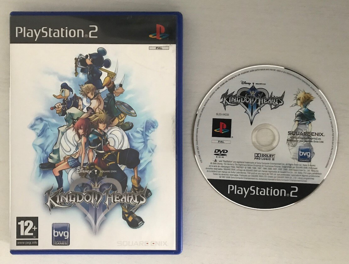
So, what’s a DVD anyway? It’s the major successor to the Compact Disc, and a result of extensive arguing between major manufacturers until they finally compromised on a common standard.
Inside the DVD
The DVD inherits the CD’s form factor but incorporates key differences that make it exponentially more useful and reliable.
First of all, the reading equipment requires a more sophisticated lens capable of resolving finer detail. It does so by housing a higher numerical aperture and a laser that produces a 650 nm wavelength (within the red spectrum) [56]. Compared to the 780 nm wavelength (near-infrared) that the CD relied upon, the DVD can condense more pits and lands to pack more information.
However, as the recorded bits become smaller, the system also becomes more sensitive to defects. Therefore, the new medium instead employs Reed-Solomon Product-Code (RS-PC) for error correction and 8-to-16 modulation for encoding data into pits and lands. Without diving into the details, both methods increase overhead in exchange for greater reliability.
As a result, a typical DVD, called DVD-5, can hold up to 4.7 GB of data. Nonetheless, the disc also supports dual layer recording, in which two data layers sit at different depths; the laser then refocuses to read one or the other. This leads to the DVD-9 variant, allowing up to 8.54 GB of storage (albeit less common for PS2 games) [57]. Finally, there’s a third format, DVD-10, which uses a single layer on both sides of the disc (similar to vinyls and LaserDiscs), but I’m not aware of any commercial game ever using it.
In any case, the PS2 drive housed two laser diodes, supporting both CDs and DVDs. So, games had a choice of either format, with developers, over time, favouring the latter one.
A long-term spec
Unlike the original CD audio, which subsequently evolved into the CD-ROM, CD-ROM XA, and more variants as needs emerged, the DVD is a unified format designed to store data using a standardised file system, typically the Universal Disk Format (UDF) [58].
Consequently, the medium supported games and movies from the get-go. That said, DVD movies adhere to a common structure called DVD-Video, which accommodates MPEG2 video, audio, interactive navigation, and copy protection. The PS2 was well-equipped for this task thanks to the IPU and SPU, but it still needed a ‘DVD player’ software to understand DVD-Video data. Sony, for some reason, didn’t implement one in the initial PS2 revision; instead, a Utility Disc was supplied within the box, which installed a player onto the Memory Card [59]. From revision SCPH-18000 (2000) onwards, the DVD playback software always came pre-installed in the BIOS ROM.
Speaking of DVD movies, you may be curious to know that the format also adopted a resolution of 720 × 480 (NTSC) or 720 × 576 (PAL), the same dimensions as Digital Television (DTV). These were selected to properly support anamorphic widescreen on contemporary televisions [60].
Network service
While Sega heavily marketed the Dreamcast around online services (even before they were ready), Sony initially left it to third parties to supply both the hardware and the Internet Service Provider (ISP) access. The hardware eventually appeared in the form of USB modems [61]. It wasn’t until a year later, in 2001, that Sony released the first-party accessory known as the Network Adaptor, providing both modem and Ethernet connectivity [62], followed by the PSBBN interface to make proper use of it. However, the latter only landed in Japan.
Similarly, game studios were in charge of providing the necessary infrastructure if they decided to provide online services (such as multiplayer). In later years, Sony deployed the Dynamic Network Authentication System or ‘DNAS’ [63]. Unlike Xbox Live, it was just an authentication system to prevent pirated games from connecting online.
An unusual kind of game
Apart from all these games with their fancy triangles, Sony also shipped a Linux distribution based on ‘Kondara’ (which is in turn based on Red Hat 6) in the form of two DVDs.
The first disc is called ‘Runtime Environment’ and the second ‘Software Packages’. The package also came with an AV Multi Out to VGA adaptor, USB Keyboard and Mouse, plus some developer manuals.
This suite was known as Linux Kit and you would run the OS by booting from the first DVD, and then proceeding as with any old-school Linux environment. Users obviously needed a hard drive fitted to install the Linux distribution, and once done, the first DVD was always required for booting this OS.
Linux Kit included Kernel 2.2.1, compilers targeting the EE (gcc 2.95.2 with glibc 2.2.2), and assemblers targeting the vector units. There was also a window system (XFree86 3.3.6) ‘accelerated’ by the Graphics Synthesizer [64]. Overall, I found this a very interesting platform. In fact, one of the research papers I consulted while writing this article was carried out using this setup.
With regards to the AV Multi Out to VGA adaptor, you may be interested to know that, while games diverged in aspect ratio, the Graphics Synthesizer supported the VESA standard, which unlike the DTV-VGA mix of the Dreamcast, used proper timings. Alas, the Multi Out’s sync signal was supplied on the green channel… so I guess no one can be perfect. Anyway, VESA provided a resolution of up to 1280 x 1024 pixels, and I imagine Linux Kit was its main target.
Finally, it’s worth noting that the futuristic PSBBN shell is based on PS2 Linux [65]. Its bootloader launches a customised PS2 Linux Kernel and then loads the PSBBN graphical interface. This makes sense, as its multimedia-rich capabilities would otherwise have had to be implemented from scratch, although I wonder whether not talking to the native OS contributed to the one-minute boot times.
Anti-Piracy and Homebrew
There’s quite a lot to talk about here, so let’s start with the DVD reader, shall we?
DVD copy protection
This area was particularly concerning for game studios, since the versatility of the DVD meant the risk of piracy was high.
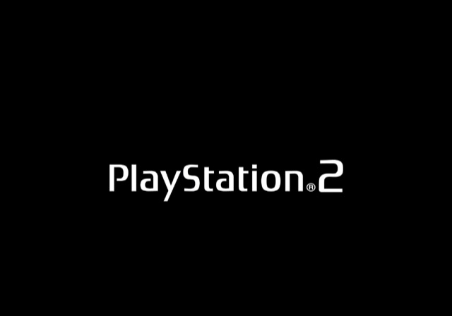
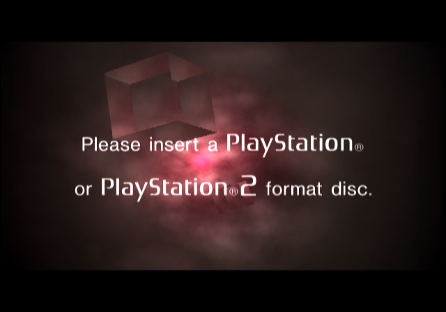
When the operating system (OSDSYS) loads a game, it does so by executing PS2LOGO from the disc [66]. This program displays the iconic ‘PlayStation 2’ logo and then proceeds to boot the game executable.
In a genuine pressed disc, PS2LOGO is stored in the first 12 sectors of the disc and encrypted with a unique per-disc key [67]. MechaCon derives the key by reading the Title ID information from the Absolute Time in Pregroove (ATIP) location on the inner part of the disc [68]. Sony altered its standard application using a proprietary frequency based on the region.
MechaCon then decrypts the executable and uses the previous information to authenticate it and validate its region. This process is abstracted away from OSDSYS, which relies on the CDVDMAN IOP driver to communicate with the DVD subsystem [69].
Circumventing protections
Having explained the most critical parts of this console, let’s take a look at multiple discovered (and commercialised) methods that defeated its protection mechanisms.
Attacking the DVD drive
As the PS2 was selling in stores, numerous third-party products started appearing with the promise to ‘unlock’ the DVD drive. With no sign to support Homebrew (outside the Linux solution), piracy was the primary beneficiary.
Modchips
As with any other console of its generation (and previous ones) using disc-based systems, it was only a matter of time before third-party companies managed to reverse-engineer the DVD subsystem. The goal here was to find a way of tricking MechaCon into believing the pirated copy was genuine, and then executing it.
This eventually materialised in the form of modchips, which lifted the copy protection checks and region-locking restrictions.
The earliest variants, such as Neo 2, treated MechaCon as a black box, relying instead on mimicking the PS1’s Wobble Groove to play pirated PS1 discs. They could also be combined with a swap trick (explained later) to boot PS2 discs. Later modchips, like Messiah, tampered directly with MechaCon and BIOS buses. In doing so, they bypassed decryption and forced the subsystem to approve the inserted disc.
Disc swapping
Amidst these advancements, yet another trick emerged. This time, it exploited the DVD drive’s handling of faulty sectors. Swap Magic resembled a ‘genuine’ disc, but its ‘game’ instructed the drive to read a non-existent executable located on a deliberately faulty sector, causing the driver to halt altogether [70]. This window of opportunity allowed users to replace the disc with a non-genuine one. Then, Swap Magic, still loaded in memory, bootstrapped the main executable of the new disc.
This did not necessarily require altering the console. However, depending on the model, the external case of the PS2 had to be altered to block the drive’s eject sensors. For some models, placing cotton wool in certain places was part of the walkthrough.
Departing from modchips
As time passed, more research about this console was gathered and shared. Consequently, new and more sophisticated discoveries led to a new wave of development that no longer relied on external hardware, at least primarily. Furthermore, piracy wasn’t the main focus anymore. Instead, the ability to run third-party programs without the approval of Sony (called Homebrew) quickly topped the goals chart.
Independence overflow
The PS2 stores a database file called TITLE.DB on the Memory Card, which contains information used to optimise the emulation of PS1 games [71]. When a PS1 game is inserted, the OS fetches the database file and loads the whole file in memory at a fixed address (strike one). The information parser is implemented using strncpy(), a function in C that copies strings (sequences of characters) from one place to another.
Those familiar with C have likely guessed where I’m going. The thing is that strncpy() doesn’t know how long a string is; therefore, unless it’s terminated (by placing \0 at the end of the sequence), the copy goes on indefinitely (with unpredictable results!). Luckily, this function accepts an optional parameter that specifies the maximum number of bytes to be copied, protecting the copy from buffer overflows. As ludicrous as it may seem, Sony didn’t use this parameter, even though each database entry has a fixed size of 256 bytes (strike two).
Upon closer inspection in RAM, TITLE.DB happens to be copied next to a saved register, $ra, which states the address to return to after the currently executing function finishes (strike three), leading to the independence exploit [72]: Craft a TITLE.DB with a large string, embed an executable within it, and structure the string so that $ra is overridden to point to the executable. If you manage to upload that file to your Memory Card (via another exploit or a PC USB adapter), you got yourself a simple Homebrew launcher.
The discovery was published in 2003. Consequently, with the slim revision, Sony shipped a new BIOS ROM revision that patched this exploit. Curiously enough, it wasn’t the last blunder to expose clumsy code.
The signature exploit
In November 2007, a hacking group began selling Memor32 [73], just another typical third-party Memory Card, except that for some reason it housed an FPGA and a USB port. It wasn’t until a firmware called Memento appeared on internet forums that the true nature of Memor32 became clear: it was designed to run unauthorised executables from the Memory Card, much like the Independence exploit.
The implementation of Memento relied on a flaw in how the signature of the DVD player is checked. It was discovered that, while binaries had to be signed using Sony’s keys, the integrity of the binary was not verified. So, anyone could replace the executable code with an alternative payload (provided it still fitted within the same allocated space), and the operating system would happily run it. The Memento firmware used this exploit to disguise its payload within the DVD player, and bundled a couple of utilities that allowed users to load games (either from the disc drive or the HDD).
However, the popularity of Memor32 and Memento was soon eclipsed once a free (and initially open-source) alternative arrived: FreeMCBoot.
The universal solution
Once Memento was reverse-engineered, an alternative that didn’t require Memor32 appeared on the internet. FreeMCBoot exploited the same vulnerability, except that it could be installed on any MagicGate Memory Card. The only drawback was that another exploit (e.g. disc swapping) was still required to bootstrap the installer.
Interestingly enough, FreeMCBoot’s user interface borrows assets from OSDSYS, thereby providing a familiar menu to launch other Homebrew. It also patches the Kernel to add APIs to access mass storage devices via the USB 1.1 ports, something many homebrew apps relied on to locate additional files.
Additionally, the installer provides two options: either to install only the files needed for the current console, or to install a global setup for all PS2 variants. Curiously enough, the latter option was challenging to accomplish [74]. Initially, the installer would fiddle with the partition table of the Memory Card to avoid running out of space, something that wasn’t particularly safe.
As luck would have it, in 2011, the security system of the PlayStation 3 had just been compromised, exposing many secrets hidden within. Among them was a collection of MagicGate keys globally used for PS2 backwards compatibility. From then on, it was no longer needed to resort to the limited DVD binary signature trick to craft PS2 executables. And so, since version 1.8b, FreeMCBoot has maintained its position as the safest and most popular method for running any type of Homebrew on a PlayStation 2.
Follow-up developments
Once the avenue for running Homebrew became more accessible, progress continued in the form of polishing previous exploits and developing Homebrew applications. Some of the latter ultimately facilitated piracy-related functionality, but they also expanded the limited capabilities of the operating system (i.e. by providing patches for games). I guess it ultimately depended on the intentions of its users.
To name a few notable examples of homebrew-related developments:
- FreeHDBoot: A variant of FreeMCBoot that instead installs on the HDD, from which the system will also try to boot.
- ps2sdk by the ps2dev group [75]: The de facto unofficial SDK for writing PS2 Homebrew without risk of copyright infringement. The project dates back to 2000, when it was only available in the form of loose libraries for accessing particular components [76], and was, over time, unified into a single package for the benefit of Homebrew developers.
- LaunchELF by multiple authors [77]: A file manager with extra utilities. It was later succeeded by ‘uLaunchELF’ and, finally, ‘wLaunchELF’.
- Open USB Loader (OPL) by multiple authors [78]: Enables to boot disc images from multiple sources (HDD, USB, i.Link, and even SMB and NMB over Ethernet) with patching capabilities.
- ESR by ffgriever [79]: Originally called ‘Vast CDVDV’, this is an application that tricks the whole system (including the DVD drive) into running a burned copy of a game without hardware modification. The original game content must be patched to disguise itself as a DVD movie (so the DVD drive doesn’t reject it), while ESR takes control of the Emotion Engine and IOP to redirect execution to the actual game.
- PSBBN Definitive Project by CosmicScale [80]: A large suite containing PSBBN with numerous patches and enhancements for seasoned Homebrew users. Not only does it make the original PSBBN interface accessible to international audiences by including English translations, but it also unlocks its limitations by incorporating many Homebrew modules that improve the experience of each area of PSBBN.
Later years also saw new exploits uncovered:
- Fortuna by krat0s [81]: An alternative Homebrew launcher published in 2019 that relies on a completely different exploit. This time, it’s a buffer overflow in the icon parser of the saves manager (part of
OSDSYS) [82]. Its main advantage is compatibility with late PS2 models that removed support for externalOSDSYSupdates (i.e. the models FreeMCBoot left out). - OpenTuna by alexparrado [83]: An open-source alternative to Fortuna originating from reverse-engineering the latter.
- FreeDVDBoot by cturt [84]: A modern vulnerability published in 2020. It consists of a new buffer overflow in the DVD player that can be exploited to perform arbitrary code execution. Users only need to burn a DVD with FreeDVDBoot to execute any binary they wish, including the FreeMCBoot installer or even ESR (Sony was very lucky that this hadn’t been discovered many years earlier! as others weren’t).
- MechaPwn by balika011 et al. [85]: The
SCPH-500XXrevision (2003) stores encrypted MechaCon firmware updates in the EEPROM. 18 years later, MechaPwn emerged to exploit theWriteConfigroutine in MechaCon to inject crafted firmware update files into the EEPROM. These disable a significant portion of the CD/DVD anti-piracy measures and region locking.- MechaCon uses a DES encryption system to store firmware updates. Thus, MechaPwn brute-forced the key to install its custom firmware.
That’s all folks
Congratulations and thank you for reaching the end of the article! To be honest, there was so much to cover that I wondered if readers would eventually get tired of PlayStation-related content after finishing this.
Anyway, in all seriousness, I do hope you discovered new things after reading this article and if you have any comments, don’t hesitate to contact me.
Until next time!
Rodrigo


