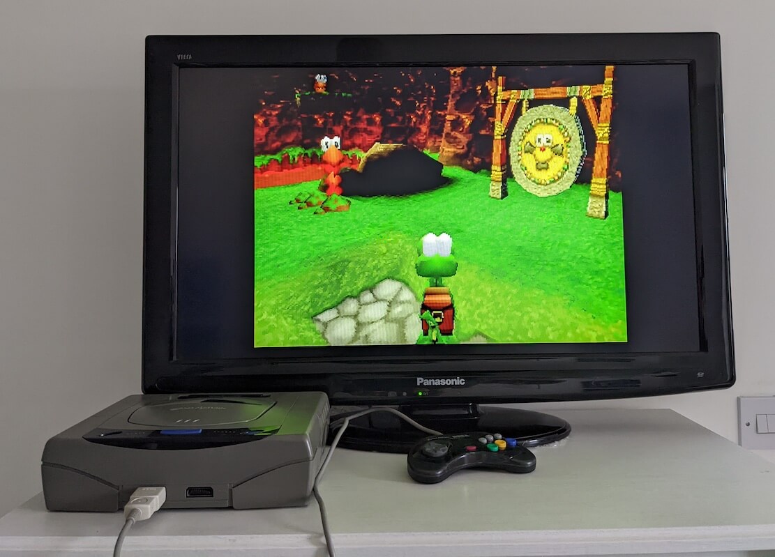
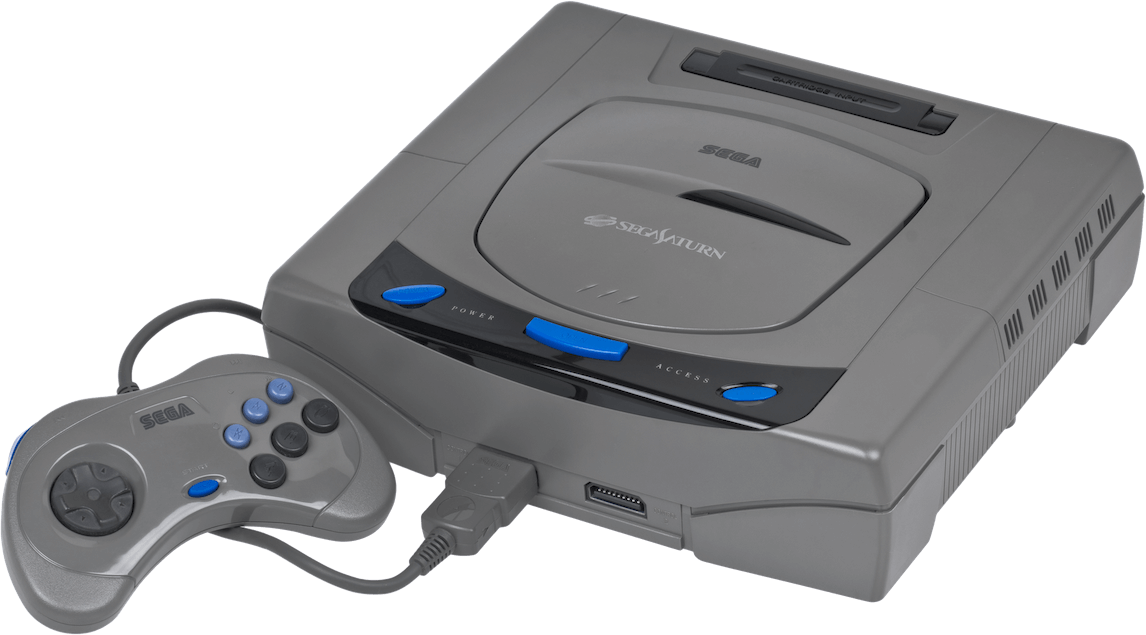
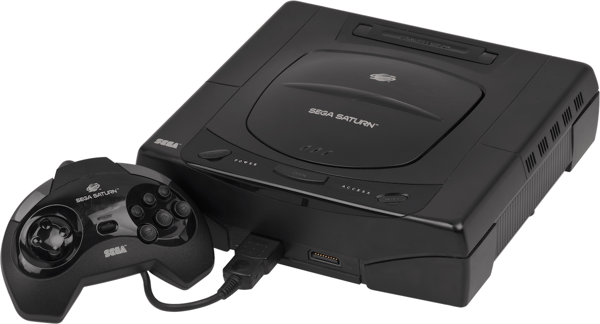
Supporting imagery
Model
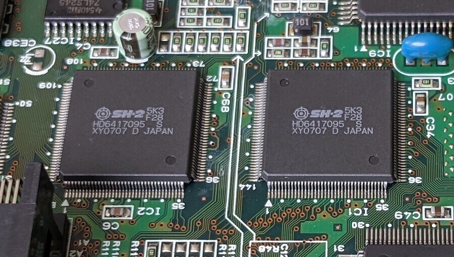
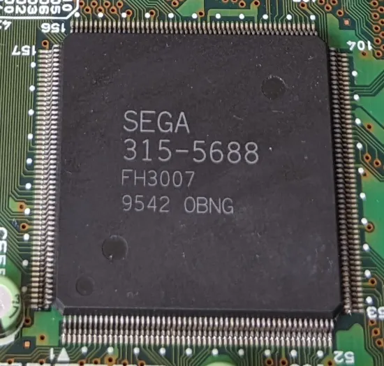
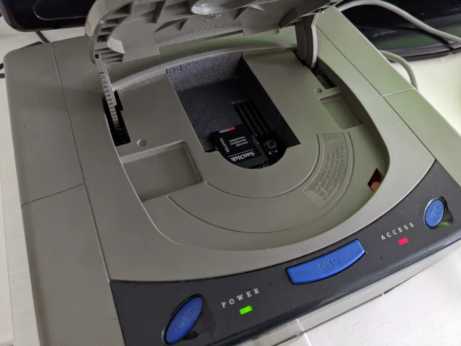
Motherboard
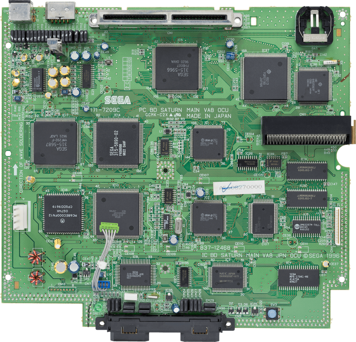
Showing 'VA8' revision which includes all components in a single board.
Remaining RAM chips are fitted on the back

Diagram
A quick introduction
Welcome to the 3D era! Well… sorta. Sega enjoyed quite a success with the Mega Drive so there was no reason to force developers to write 3D games right now.
Just in case developers wanted the extra dimension, Sega prepared some bits of the hardware to enable polygon drawing as well. Hopefully, the result didn’t get out of hand!
CPU
Just like its close competitors drowned in options during the RISC fever, Sega had to go through all the conundrums of choosing a new vendor that could deliver the next generation of games (including those with ‘3D’ capabilities). In the end, the company chose a fresh CPU whose creator was desperately seeking an adopter: the Hitachi SuperH, or ‘SH’.
While initially focused on embedded applications, Hitachi’s new creation debuted modern arts such as [1]:
- A load-store architecture, meaning instructions don’t mix memory and register operations, resulting in a cleaner and scalable CPU design. This is one of the pillars of RISC CPUs.
- A 32-bit data bus and Arithmetic Logic Unit (ALU), enabling the flow and operation of larger amounts of data (32-bit values) without consuming extra cycles.
- 16 general-purpose 32-bit registers, this time more flexible than those found in previous CPUs, such as the Motorola 68000. This is another design decision derived from the RISC guidelines [2].
- 32-bit address bus, allowing up to 4 GB of memory to be addressed (farewell mappers).
- A pipelined data path with five stages: The execution of instructions is now divided into five steps, or stages. The CPU can queue up to five instructions simultaneously, with each one assigned to a different stage. This allows taking advantage of all the CPU’s resources without idling, while also increasing the number of instructions processed per unit of time.
- A 16-bit multiplication unit: Performs multiplications with 16-bit integers.
Furthermore, the SuperH features a new instruction set called SuperH ISA which, apart from adopting a RISC design, all of its instructions are 16 bits wide. This comes as a surprise since this CPU operates 32-bit words, so you would expect instructions to have the same length. Yet, Hitachi managed to fit its ISA using half the size. Not only does this format reduce the size of programs, but since the CPU fetches instructions in 32-bit batches, two instructions can be retrieved in one cycle. Overall, this technique of compressing the instruction set helped tackle a common concern of RISC-based architectures called ‘code density’, where the latter required more instructions (therefore, more memory) to perform the same tasks as non-RISC systems.
The ramifications
Conversely, other drawbacks of RISC designs are still present in the SuperH, such as control hazards. Consequently, programs are required to include branch delay slots to avoid calculation errors. To remedy things, the SuperH features delayed branch instructions which are branch instructions pre-fitted with a delay slot [3].
Data hazards are also present but not tackled by the programmer or compiler; the CPU will automatically stall the pipeline whenever necessary.
Sega is not satisfied
Nevertheless, all of that didn’t stop Sega from expressing dissatisfaction with the end product. This was mainly due to the small 16-bit multiplier, which was seen as a bottleneck when processing larger amounts of data (a new need for 3D games). Thus, Hitachi synthesised a second revision with an extended multiplier unit and other features from Sega’s checklist [4], leading to a new CPU called SH-2.
Even so, Sega couldn’t stand still after hearing what choice of CPU its competitors went for. So, it asked Hitachi to step up the clock frequency of the SH-2 - an impossible task once the chip is already out for manufacturing. Luckily, Hitachi had another trick up their sleeve: multiprocessing. During the research phase of the SH, the team added minimal circuitry to allow the SH to work alongside other SHs within the same system simultaneously. Upon hearing that, Sega decided on a two-chip configuration for the Sega Saturn. And the rest is history.
The final product
Having explained the origins, let’s take a look at the shipped product.
This console has not one but two Hitachi SH-2 CPUs running at ~28.63 MHz each [5]. While both physically identical, they are placed in a master-slave state, where the first one may send commands to the second one. This can achieve some degree of parallelism, albeit both sharing the same external bus [6] (which is prone to congestion).
Hitachi packaged different variants of the SH-2 and sold them as part of a series called ‘SH7600’. All of them feature [7]:
- The aforementioned five-stage pipeline and SuperH ISA. The latter has been extended with six additional instructions for specialised branching and arithmetic.
- An upgraded 32-bit multiplication unit, which now performs multiplication with 32-bit integers.
- A 32-bit external data bus that is shared across the two CPUs.
The specific chip selected for this console, the ‘SH7604’, contains the following additions [8]:
- 4 KB of cache: Stores a small number of instructions and data previously fetched from memory to speed up future reads.
- A 32-bit division unit: Performs division with 32-bit integers.
- An internal Direct Memory Access (DMA) controller: Transfers data from memory without the intervention of the CPU.
- Support for little endian, enabling the CPU to understand values encoded in the opposite order. This is useful when external memory is shared with other processors.
It’s worth pointing out that having two CPUs doesn’t mean that games will work twice as fast! In practice, however, this requires very complex programming to efficiently manage CPUs that share the same bus. For instance, memory access should leverage the cache as much as possible.
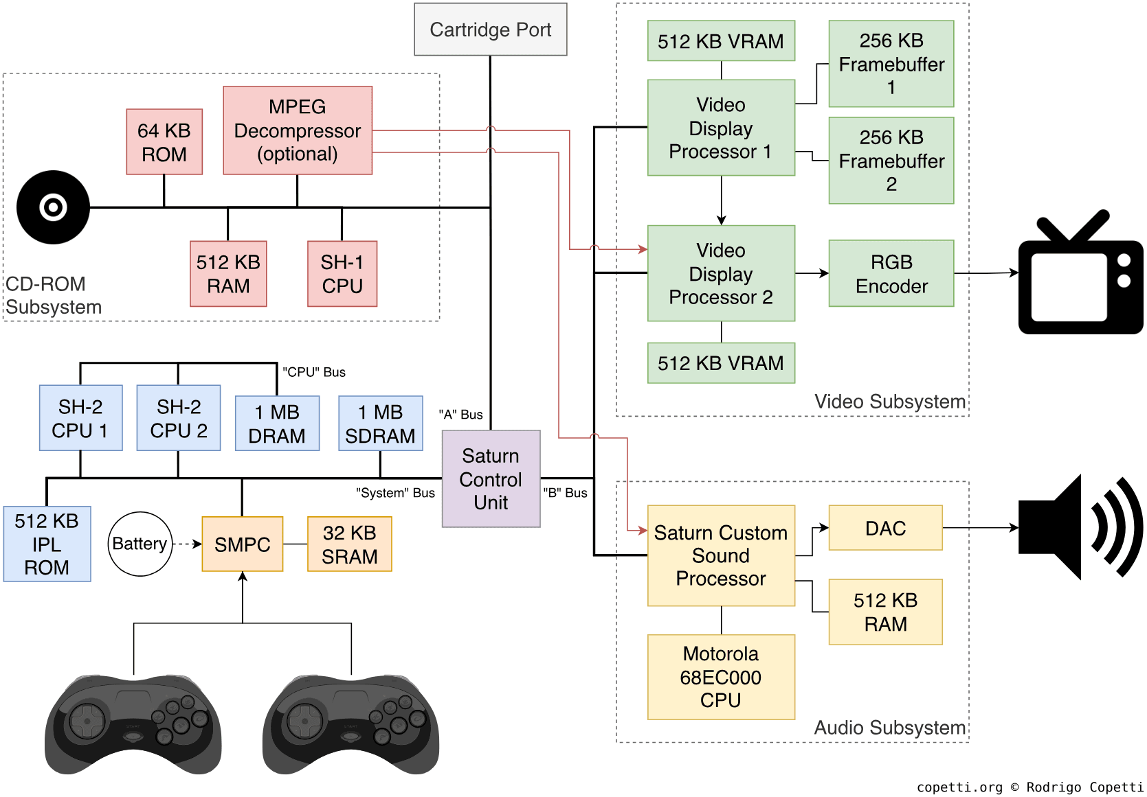
The octopus architecture
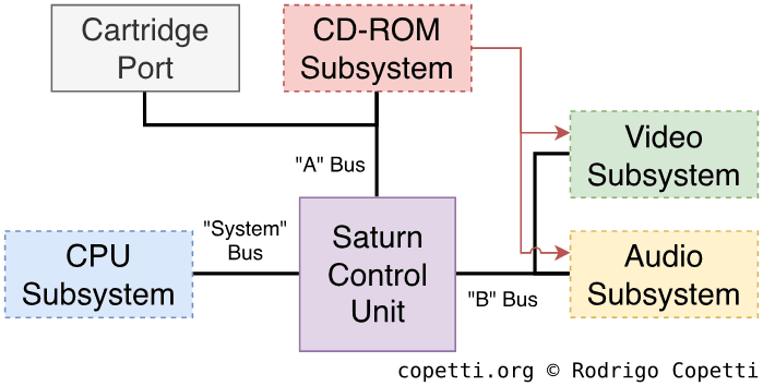
The Sega Saturn houses a significant number of processors (eight!). So, to avoid making them fight for resources, engineers grouped the circuitry into four separate subsystems:
- The CPU subsystem, where the main CPUs and memory reside. Truth be told, there’s also an unusual third component. This is explained further down.
- The Video subsystem, comprising the graphics accelerators.
- The Audio subsystem, which can be considered a separate computer in its own right (you’ll see more in the ‘Audio’ section of this article).
- The CD-ROM subsystem, a walled fortress owing to the copy-protection mechanisms implemented. These are explained further in the ‘Anti-piracy’ section.
It’s worth noting that each subsystem is wired to a dedicated bus - except the Video and Audio ones, which share one.
A divided choice of memory
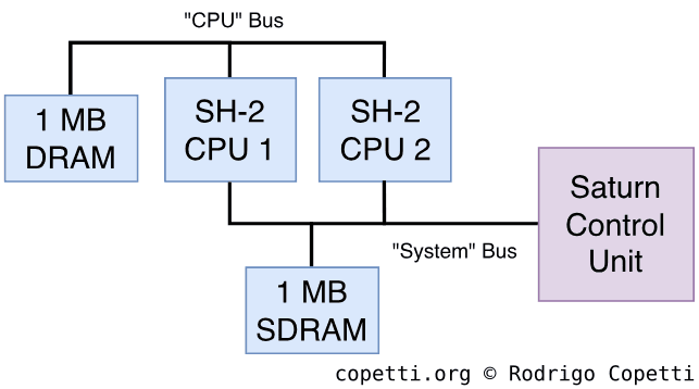
The CPU subsystem contains a total of 2 MB of RAM for general-purpose use, called Work RAM (WRAM). But it’s not that simple: this memory is split into two distinct blocks and, once again, each is accessed via different buses:
- The first block provides 1 MB of Synchronous DRAM (SDRAM). Due to its higher access speed, this block is also called WRAM-H. Its bus is shared with other components.
- The other megabyte is named WRAM-L, as it uses Dynamic RAM (DRAM) instead, resulting in lower rates. Its bus, however, is reserved for the main CPUs.
The third processor (and counting)
Surprisingly, it seems that the two SH-2 CPUs still weren’t enough for Sega. So, to accelerate vector processing (at the cost of more complexity), the CPU group also houses an additional coprocessor, the Saturn Control Unit or ‘SCU’.
This is a separate chip comprised of two modules [9]:
- A Direct Memory Access (DMA) controller: Arbitrates access to WRAM-L across the three subsystems without the intervention of the CPUs.
- A Digital Signal Processor (DSP): Used as a fixed-point ‘geometry unit’. Compared to the SH-2, it performs matrix/vectors calculations such as 3D transformations and lighting faster. However, it runs at half-speed and its instruction set is more complex. Furthermore, it depends on the SH-2’s slow WRAM-L to fetch and store data (using the DMA).
To alleviate things, the SCU comes with 32 KB of Static RAM (SRAM) for local use.
Graphics
Since the Saturn is the first ‘3D console’ reviewed for this series, let us first go over the fundamental design changes that made way for the new generation of 3D graphics.
Revised methodologies
Firstly, the GPU now relies on a frame buffer: graphics are no longer required to be rendered on the fly. Instead, the GPU reserves a portion of Video RAM (VRAM) to draw a bitmap containing all the computed geometry requested by the CPU. A video encoder then picks up that region and outputs it through the video output signal. Be that as it may, the Saturn does mix the two models… I will explain more later.
Consequently, having this reserved ‘working space’ allows the GPU to continue manipulating the bitmap even after finishing rendering the scene, enabling the CPU to offload additional exhaustive tasks (such as lighting and anti-aliasing) to the GPU. Here is where the concept of graphics pipeline starts to gain significance.
Secondly, more VRAM is required: Using a frame buffer increases memory requirements (which is no longer a major issue). The amount of RAM required for a frame buffer is proportional to the screen dimensions and the number of colours used (a.k.a. colour depth). As an example, 600 KB of VRAM can contain a frame buffer of 640x480 pixels at 32k colours (16 bits per pixel).
Additionally, programmers are free to organise their VRAM usage: not every bit must be allocated for the frame buffer. So, why not also use it to cache textures, render other frame buffers concurrently, and add colour lookup tables to speed things up?
Finally, the CPU incorporates vector operations: a GPU with 3D capabilities would be incomplete without a CPU capable of feeding the required geometry. For this reason, next-generation CPUs feature some form of specialised instructions that accelerate vector calculations; these are known as Single Instruction Multiple Data (SIMD) extensions. Nonetheless, their design across the industry will be far from standardised.
In the case of the Saturn, vector operations are accelerated by the Saturn Control Unit, not the SH-2 CPUs.
Sega’s offering
This console includes two proprietary GPUs: the VDP1 and VDP2. Each serves a different purpose while operating concurrently. Some might argue that the new GPUs are an evolution of the classic VDP, while others may claim it’s a complete redesign… I think it’s a bit of both.
With that in mind, let’s take a look at the two chips.
VDP1
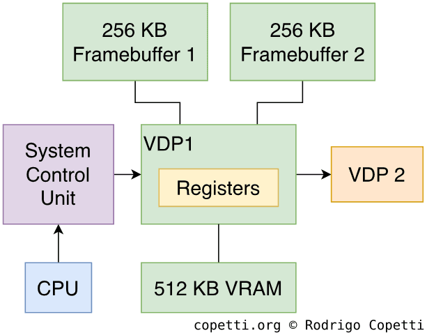
The Video Display Processor 1 (VDP1) is a chip that draws sprites with geometric transformations [10]. The results are written to a frame buffer, which is subsequently streamed to the VDP2 for display.
This chip is programmed by issuing drawing commands. So, programmers are provided with 512 KB of dedicated RAM to store these commands, along with the necessary materials (textures/tiles, colour lookup tables, etc.) to process them.
Consequently, the VDP1 is designed to use quadrilaterals as primitives, meaning it can only compose models using only four-vertex polygons (sprites). The chip applies Forward Texture Mapping to connect texture points onto the quadrilateral, in that direction. It doesn’t come with any filtering or interpolation techniques, so the rendering is subject to aliasing.
The VDP1 also provides this selection of effects:
- Two shading algorithms (Flat and Gouraud) for lighting.
- Anti-aliasing: In this case, it duplicates pixels to cover gaps during texture mapping.
- Clipping to discard polygons outside the camera’s viewport.
- Transparency to blend two non-opaque bitmaps.
Two 256 KB frame buffer chips are available to concurrently draw new scenes of the game without breaking the current one being displayed. When the secondary buffer is finished being drawn, the VDP1 switches to broadcasting that one instead, and the cycle repeats. This technique is called page flipping.
VDP2
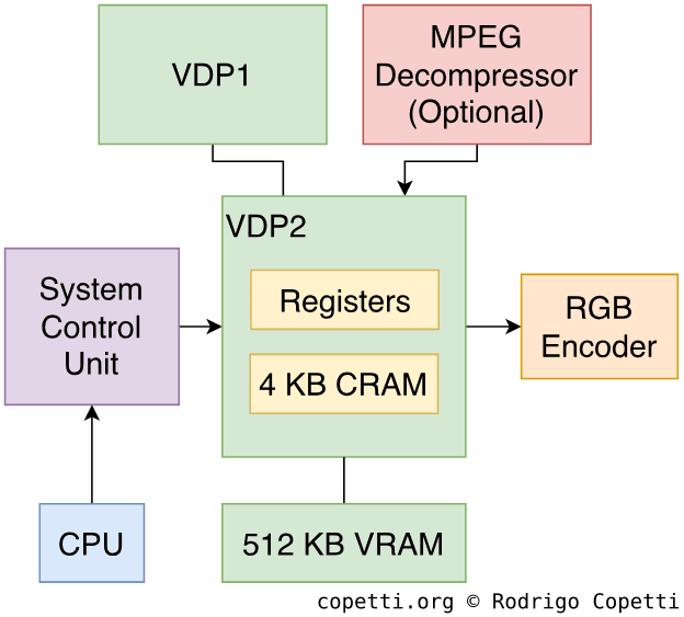
The Video Display Processor 2 (VDP2) specialises in rendering large planes (up to 4096×4096 pixels) with transformations (rotation, scaling and translation) applied [11].
More importantly, the VDP2 renders on the fly (without a frame buffer), much like earlier tile-based engines. It supports up to 16.7 million colours (24-bit).
This chip is also responsible for displaying the VDP1’s output buffer, which can itself be transformed and mixed with the VDP2’s layers. The VDP2’s ‘frame’ consists of up to four 2D planes and one 3D plane, or just two 3D planes.
This chip relies on tile-maps to compose planes and applies perspective correction for 3D texture mapping. This is a more sophisticated approach that accounts for the depth value when computing rotations.
Effects available include:
- Multi-texturing for mapping more than one texture onto a single polygon.
- Shadowing: after the VDP2 receives the sprites generated by the VDP1, it can reduce their brightness and blend them with half-transparency.
- Nonetheless, the VDP2 only receives a sprite stream from the VDP1 (in pace with the CRT beam) so this function tends to be tricky to encode and operate.
This chip also houses 4 KB of Colour RAM (CRAM) which is used to translate the VDP1’s custom colour values (indexed colours) into 24-bit RGB colours.
Finally, even though the VDP2 is limited to two 3D planes, nothing prevents the CPU from using its VRAM as a software-based frame buffer to render additional 2D or 3D graphics.
If this section got your attention, I recommend checking out the sources at the end, the VDPs have a lot more interesting quirks that lie beyond the scope of this article.
Defining the problem
As you can see, the architecture of the graphics subsystem is quite complex, and its interpretation often varies depending on the needs:
As a powerful 2D console
The capabilities of the Saturn for drawing 2D scenes were vast compared to those of the Mega Drive or SNES, although they were not the console’s main selling point.
For a quick demonstration, I will use Mega Man X4 (1997) as an example.
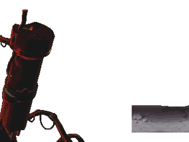
Sprites
In this case, the VDP1 is tasked with plotting traditional sprites without any 3D distortion applied.
The CPU sets up the VDP1 by writing to its registers and populating its VRAM with commands and tiles. The process can also be accelerated using the DMA controller.
Backgrounds
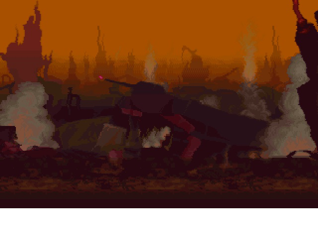
The VDP2 is then instructed to draw background planes. These, together with the sprite layer, are automatically composited to form a fully coloured scene.
The commanding part is fundamentally similar to that of the VDP1: programmers have access to registers and VRAM to configure the chip accordingly.
Certain VDP2 functions can be exploited to create more realistic scenery, such as scaling effects to simulate a heat haze, as seen in the ‘2D plane 2’.
Result
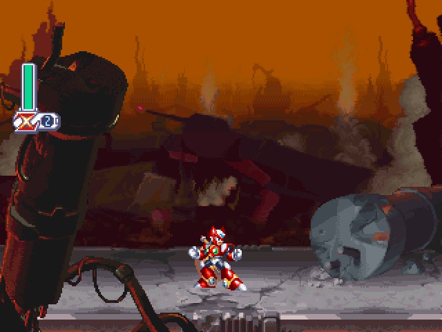
Not much mystery here, the VDP2 handles the last step of passing the processed signal to the video encoder.
The VDP2 operates in sync with the CRT beam, meaning that its ongoing computations correspond to the pixels due to appear on the upcoming scan line.
As a challenging 3D console
Here’s where the Saturn both shone and struggled at the same time. While this console had eight processors to take advantage of, it ultimately came down to:
- Whether programmers would be able to master most of the console’s features during a small time frame (remember the console’s commercial lifespan would effectively end once its successor was released, or even announced).
- Whether their game could ship within a reasonable date.
For this reason, game quality varied dramatically from title to title, with each studio coming up with unique approaches.
3D modelling
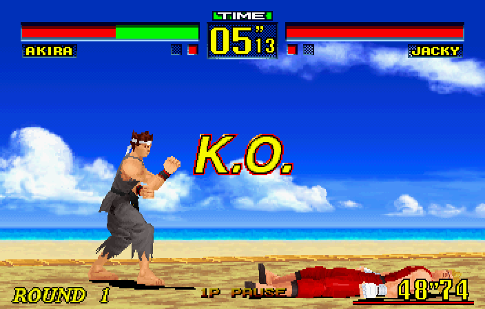
Virtua Fighter Remix (1995).
So far, previous examples used individual regular quadrilaterals to form sprites and/or background layers. But what if we group multiple irregular primitives and arrange them to form a more complex figure? This is how 3D models come to fruition.
To put it in simple terms, classic 2D consoles like the Super Nintendo arrange their graphics (backgrounds and sprites) in quasi-rectangular areas. In some cases, such as with Mode 7, programmers can supply a rotation matrix to apply transformations to some of these areas. The Saturn, by contrast, allows developers to define four-point quadrilaterals with arbitrary angles between their edges - Sega calls them distorted sprites. Then, the VDPs’ texture-mapping capabilities paint the quadrilateral’s area with a texture, which is scaled to conform to the polygon’s shape.
In terms of operations required in a 3D game, the CPUs and SCU are tasked with formulating a 3D world and projecting it onto a 2D space. Then, both VDPs are commanded to render it, apply effects, and finally broadcast it to the television.
Pixel processing
Virtua Fighter Remix (1995).
Either VDP can draw the newly projected 3D space and stamp textures and effects. However, which chip is ‘in charge’ varies from game to game.
Some developers prioritised the VDP1 for rendering nearby polygons, leaving the VDP2 to handle distant scenery. Others devised clever workarounds that allowed the VDP2 to draw closer polygons (thereby offloading the volume of geometry passed to the VDP1). The core challenge lies in designing an efficient engine capable of displaying impressive graphics while maintaining an acceptable frame rate.
The new designs
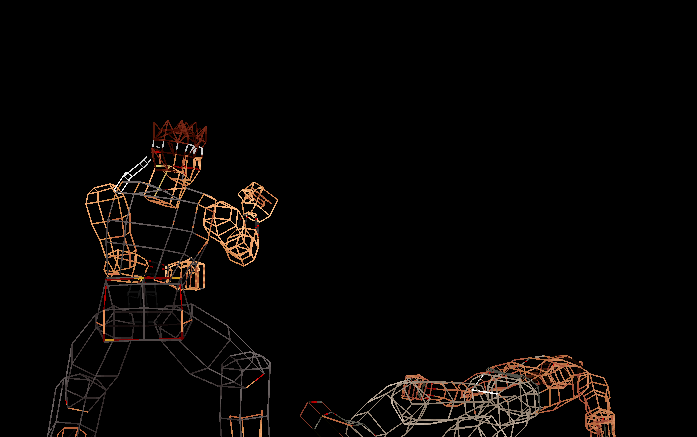
These are some examples of characters that were redesigned specifically for this console. I initially built an interactive model viewer for the website edition, and later adapted the visualisations for the physical formats.

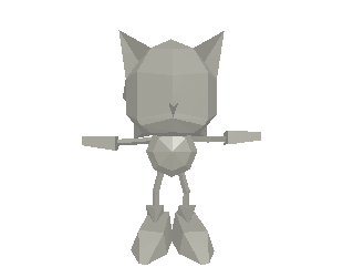
 Interactive model available in the modern edition
185 quadrilaterals.

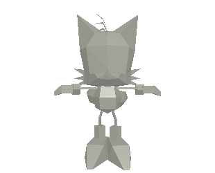
 Interactive model available in the modern edition
254 quadrilaterals.
While the Saturn is only able to draw quadrangles, the Wireframe view exhibits two triangles in place of a single quadrangle. This occurs because the modern format used to encode this model (glTF, an open standard for contemporary 3D modelling), allowing modern devices to still render it, doesn’t support quadrangles at the time of this writing. This behaviour is not apparent in the Surface view.
In a way, this highlights how modern graphics technology can struggle to faithfully emulate their ~30-year-old predecessors!
An introduction to the visibility problem
When 3D polygons are projected onto a 2D space, it is crucial to determine which polygons are visible from the camera’s perspective and which are hidden behind [12]. Otherwise, models are not drawn correctly, effects like transparency appear broken, and hardware resources are wasted.
This process is widely known as Visible Surface Determination or ‘VSD’, and it’s a fundamental challenge in the field of computer graphics. Numerous publications describe algorithms that tackle this issue at different stages of the graphics pipeline - some offering highly accurate results, while others sacrifice precision in favour of better performance.
Now, unlike academic or professional-grade equipment, consumer hardware is severely constrained, meaning the choice of algorithm is often restricted to only a few options… or none whatsoever.
The Sega Saturn’s approach is what I consider a semi-solved case. The VDP1 doesn’t implement any VSD functionality: you either feed the geometry in the correct order or you get a mess. However, Sega provided a graphics library known as ‘SGL’ that implements a solution called Z-sort or Painter’s algorithm [14]. This performs polygon sorting in software.
Essentially, SGL allocates a buffer to sort polygons by their distance from the camera (arranging them from furthest to nearest). Then, it issues the corresponding display commands to the VDP1 in that order.
One of the limitations of Z-sort in 3D environments is that its distance value (Z-order) is only approximated, meaning graphic glitches may still appear. For this, programmers may skip SGL in favour of implementing their own algorithms.
In later articles, you will see alternative approaches to visible surface determination. Some still rely on software, while others benefit from hardware acceleration.
The transparency issue
As part of its own set of colour math, the Sega Saturn is capable of rendering half-transparent graphics - that is, blending overlapping layers of colours to give the illusion we can see through them (a.k.a. translucency). However, there are significant caveats to this functionality [15]:
- Only the VDP2 can blend pixels with half-transparency, while the VDP1 only outputs a rendered buffer, with no distinction between overlapping sprites. As a result, overlapping half-transparent sprites occlude the ones beneath.
- The VDP1’s forward texture-mapping process corrupts half-transparency when applied to distorted sprites (i.e. polygons).
- Half-transparent pixels require six times longer to draw.
As a workaround, 2D games can activate the ‘mesh’ property on a texture. With meshed textures, the VDP1 sets the odd X/Y texture coordinates as ‘fully transparent’ (i.e. empty), allowing layers beneath to appear through. Curiously enough, when the console is connected to the television via the composite video signal (a standard at the time, aside from RF) the mesh pattern appears blurred. This accidental but effective consequence provided a way to simulate half-transparency [16].
Nevertheless, the opaque portions of a mesh would still occlude other sprites. Moreover, this didn’t resolve the issue for 3D games. In the end, some titles had no option but to ditch half-transparency altogether… yet some studios found ingenious fixes, take a look at these two cases.
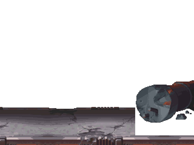
In both examples, the game commands the VDP1 to draw foreground objects and background scenery. In turn, the VDP2 renders the landscape imagery far away, and overlays the HUD statistics in front of the 3D models. Consequently, the VDP1’s 3D models (rendered as distorted sprites) are unable to employ half-transparency; this prevents them from naturally blending with the VDP2’s layers.
Nevertheless, the two games exhibit different behaviour. During gameplay, the background of Daytona pops out of nowhere (as half-transparency is disabled). In contrast, Sonic R achieves not only half-transparency but also a fading effect. Traveller’s Tales devised a workaround by adjusting the ‘mix ratio’ registers of the VDP2 (used for defining the texture’s alpha) and manually switching the lighting levels as the character gets closer [17].
Audio
The audio capabilities of this console were part of a broader digital revolution taking place during the same period. In essence, the combination of new storage formats and affordable (yet sophisticated) sample synthesisers ultimately unlocked the composers’ ability to produce their music in-house, and then incorporate it directly into games in its original form.
The tech stack
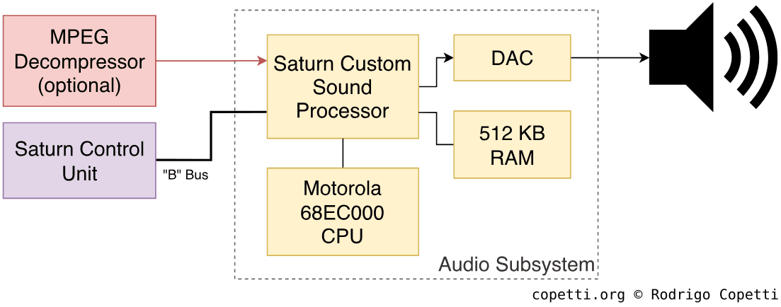
Be that as it may, beneath the surface of attractive functionality lies a complex arrangement. In the case of the Sega Saturn, its sound subsystem is composed of several parts [18]:
- The Saturn Custom Sound Processor (SCSP): Also referred to as the Yamaha YMF292, it’s composed of two modules:
- A multi-function sound generator: Processes up to 32 channels with PCM samples (up to 16-bit at 44.1 kHz - a.k.a. ‘CD quality’) or FM channels. In the case of the latter, a subset of channels is reserved for operators.
- This component provides pitch scaling, envelope generator, Low-Frequency Oscillator (LFO), and volume and stereo panning.
- A Digital Signal Processor (DSP): Applies audio effects such as echo, reverb, and chorus. The documentation also mentions ‘filters’, but it’s unclear whether this means envelope or frequency-based filters (e.g. low-pass).
- A multi-function sound generator: Processes up to 32 channels with PCM samples (up to 16-bit at 44.1 kHz - a.k.a. ‘CD quality’) or FM channels. In the case of the latter, a subset of channels is reserved for operators.
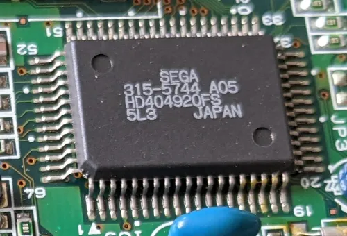
- A Motorola 68EC000: Controls the audio components and interfaces with the main CPUs. It executes a sound driver to operate the neighbouring modules.
- 512 KB of RAM: Named ‘sound RAM’, it’s used to store the sound driver and audio data (e.g. PCM samples). It also serves as a working area for the DSP.
In a nutshell, the audio pipeline works as follows:
- Either main CPU initialises the aforementioned components and loads a sound driver into sound RAM. It then activates the Motorola 68EC000, so it can begin working.
- During gameplay, the audio subsystem may receive data in the following ways:
- The main CPU can instruct the Saturn Control Unit (SCU) to transfer PCM samples (or other data) from the CD to sound RAM.
- The CD subsystem may send audio data from uncompressed audio tracks (called CD-DA) directly to the SCSP.
- If the ‘Video CD’ card is installed, the CD subsystem can forward compressed audio to the card, which in turn decompresses it and passes it on to the SCSP.
- Based on the sound driver running and the data received, the Motorola 68EC000 tasks the SCSP to generate the audio. This may involve allocating channels for FM synthesis or PCM playback, both of which have many effects at their disposal.
The opportunity
As previously mentioned, the new audio subsystem allowed studios to finally record and produce soundtracks in-house, then bundle them in the game without the need for rearrangement - unlike earlier systems that relied on constrained sequencers or sound hardware with strict synthesis methods.
This shift was made possible thanks to a combination of key factors:
- The adoption of CD-ROM as storage medium for games allowed developers to store large and high-quality soundtracks.
- The audio endpoint could receive and mix PCM data with acceptable fidelity.
- The audio subsystem offered sufficient power and bandwidth to stream compressed PCM data and decode it in real time.
Operating System
Upon powering on the console, the first component that starts up is the System Management and Peripheral Control (SMPC), a 4-bit microcontroller that takes care of initialising nearby chips, such as switching on the two SH-2s and setting them in a ‘master-slave’ configuration [20].
Afterwards, the reset vector of the master SH-2 is set to 0x00000000 [21], which points to a 512 KB ROM chip containing the Initial Program Loader (IPL).
The IPL performs the following functions as part of the boot sequence [22]:
- Finish initialising the hardware.
- If a cartridge is inserted and contains executable code, continue booting from there.
- If a ‘Video CD’ card is inserted, boot it.
- If a disc is inserted, verify that it’s genuine.
- While at it, the system displays the splash screen animation.
- If the disc is genuine, boot the game.
- If the disc is not genuine or there’s no disc inserted, launch the interactive shell.
Interactive shell
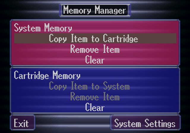
Alternatively to playing games, the Saturn included a built-in music player called ‘Multiplayer’, from which users could also access a save data manager.
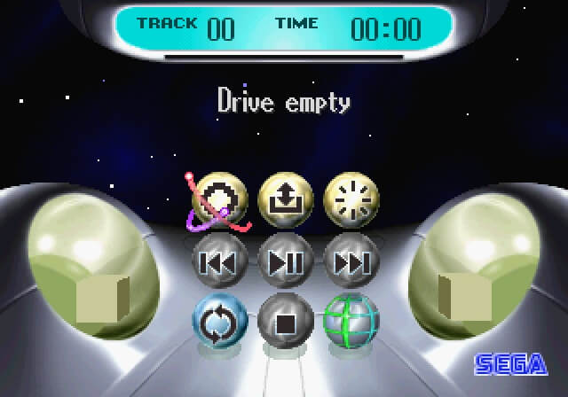
If a Video CD card was inserted, Multiplayer could also reproduce MPEG video decoded from the card itself.
No BIOS?
Unlike the PlayStation, whose ROM chip bundles a BIOS that exposes APIs for programmers to use, the Saturn’s ROM is often referred to as ‘IPL’ instead - presumably since its main job is to initialise the system, bootstrap the game, and run the shell.
However, the IPL ROM also stores some routines (called services) to manipulate the hardware, such as managing save data and power control. It even implements a semaphore mechanism for synchronising operations across multiple processors simultaneously. Hence, that part of the ROM is called System program.
Games
Official Sega Saturn games are loaded from the 2x CD-ROM drive. Its medium, a tailored variant of the Compact Disc (CD), has a capacity of 650 MB [23] and adheres to the ISO 9660 standard for storing data [24]. Additionally, many games include audio tracks next to the data tracks to stream uncompressed audio during gameplay.
The Compact Disc (CD)
Co-authored by the Dutch company Philips and the Japanese company Sony, the Compact Disc (CD) is an optical medium on which information is stored by engraving microscopic pits and lands into its polycarbonate surface [25]. An infrared beam is then directed from the drive, and the reflection produced on the CD’s surface is used to retrieve the information.
The process of converting digital information (ones and zeroes) into pits and lands, and vice versa, is by no means simple, especially since CDs must:
- Allow plenty of capacity to make them a competitive alternative to existing media.
- Notably, the first revision of the specification (CD-DA) only strived for 74 minutes of high-quality audio, while the later format (CD-ROM) allowed for 650 MB of general-purpose data.
- Be robust enough to sustain day-to-day damage and intensive use.
- Be reliable enough to store any kind of information without fear of data loss.
Thus, on the surface, data is encoded using the Non-Return-to-Zero inverted (NRZI) scheme [26]. This means the bitstream consists of zeroes until a land-to-pit or pit-to-land transition occurs, at which point a 1 is appended instead.
Beneath the surface, however, things become more complex. NRZI looks manageable on paper, until the optical reader encounters a sequence of ones (continuous pit and land changes) or long sequences of zeroes (constant pits or lands), at which the sensor will struggle to detect or remain synchronised, respectively. To address this, a preliminary step called Eight-to-Fourteen Modulation (EFM) is added to the mix. EFM translates every possible combination of 8 bits into a 14-bit sequence that takes into account the constraints of the CD reader. Consequently, before data is engraved, groups of 8 bits are converted into a sequence 14 bits, after which three ‘merging bits’ are inserted between the encodings. All in all, the resulting engravings provide high data density while also keeping the CD reader synchronised.
Finally, with regards to reliability and robustness, the CD also employs Cross-Interleaved Reed-Solomon Coding (CIRC), which spreads data across the disc and adds redundancy so that damaged regions can be reconstructed.
I have to say, the evolution of optical storage is an interesting topic in itself, and as the CD evolved into the DVD and beyond, advanced mechanisms for sensing, encoding, and error correction made its way into consumer hardware - culminating in standards that dominated game distribution across multiple generations.
The Saturn’s CD
So far, I’ve been discussing the wider standard, but in the case of the Saturn, Sega adopted the CD‑ROM XA format (short for ‘CD-ROM eXtended Architecture’). This is a superset of the CD‑ROM format that allows to store data, uncompressed audio, and interleaved multimedia tracks [27]. The latter is essential for slow‑speed drives, allowing audio and images to be streamed at a reasonable rate, a capability particularly useful for video playback. Speaking of, video playback must still be decompressed, and for that Sega shipped an optional card called ‘Video CD’.
Development
At first, Sega did not provide comprehensive software libraries or development tools (in fact, the initial documentation contained several inaccuracies), meaning the only way to achieve acceptable performance was through harsh assembly. Eventually, Sega shipped a complete Software Development Kit (SDK), hardware kits and additional support libraries to ease I/O and graphics operations.
That said, Sega Saturn games were ultimately written using a combination of C and various assembly languages targeting individual components.
I/O
Peripheral management and Real-Time Clock (RTC) are also provided by the aforementioned System Management and Peripheral Control (SMPC), which is controlled via commands sent by the SH-2s.
Expansion methods
This console bundles a considerable number of external connectors and interfaces, most of which only saw a handful of uses:
- Behind the drive, there is a cartridge slot, officially intended for additional storage (save data) or extra RAM. In Japan and the United States, a modem was also offered to provide online connectivity.
- At the rear of the console, there is a slot for a Video CD Card, which performs MPEG decompression for programs or games that support it.
- Finally, there is a mysterious socket at the back of the console called Communication Connector. Although Sega did not publish any developer documentation, reverse-engineering efforts revealed that it connects to the SCSP’s MIDI pins and the Serial Interface (SCI) of two SH-2’s [28]. In any case, Sega released a floppy drive that made use of this interface.
Anti-Piracy & Homebrew
In response to the ease of cloning a CD, Sega implemented a copy protection system - along with region locking - to control the distribution of its games.
For the copy protection itself, Sega deliberately deviated from the standard CD format, making it impossible for regular CD burners to produce a perfect copy of a Saturn game. Then, as part of its verification process, the Saturn’s disc reader looks for these non-standard features.
To be more specific, Saturn discs were manufactured with an unusual data pattern pressed into the outer edge [29], creating a visible ring engraved with trademark labels. This ring sits outside the standard data area of a CD (known as the ‘Program Area’) and beyond the Lead-out section, which signals the end of readable data. As a result, conventional drives couldn’t access or replicate that part of the disc.
Inside the Saturn’s disc drive is a dedicated SH-1 processor that verifies the presence of the ring independently from the main CPUs. It uses obscure communication protocols to talk with the rest of the system. This check, however, is only performed once.
Defeat
To begin with, the classic method used for disabling the copy protection consisted in installing a mod chip, which could deceive the CD reader when any type of disc was inserted. Another technique, known as the ‘swap trick’, consisted in hot-swapping a genuine disc with a burned one immediately after the protection checks had passed… with the risk of damaging the drive.
After the turn of the century, more sophisticated methods for running unauthorised code were discovered, for instance:
- An exploit in the copy protection mechanism was identified, allowing to boot up any disc game without undergoing copy protection checks. This was subsequently implemented in the form of a cartridge called PseudoSaturn [30]. As it relied on the cartridge medium, Action Replay cartridges were often re-flashed with PseudoSaturn (though the flasher program still needed to be bootstrapped somehow, most commonly through the swap trick).
- This method remains in use as of 2022, although a newer fork named ‘Pseudo Saturn Kai’ is installed instead.
- Another method emerged in 2016 (almost 20 years after the console’s release) by exploiting the fact that the Video CD add-on can inject unencrypted code into the CD subsystem (bypassing the CD drive entirely). This finally allowed users to load Homebrew independently of the ageing drive. The Video CD exploit is commercially distributed as a product called ‘Satiator’ (I’m not sponsored, by the way).
- Lastly, there’s a commercial alternative that replaces the CD reader with an SD or SATA adapter. The Saturn still thinks it’s reading from a CD, but the ‘CD’ is being emulated by the adapter, which is in turn reading from a disc image [31]. These products are known as Optical Drive Emulators (ODE).
That’s all folks