Supporting imagery
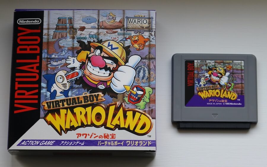
Model
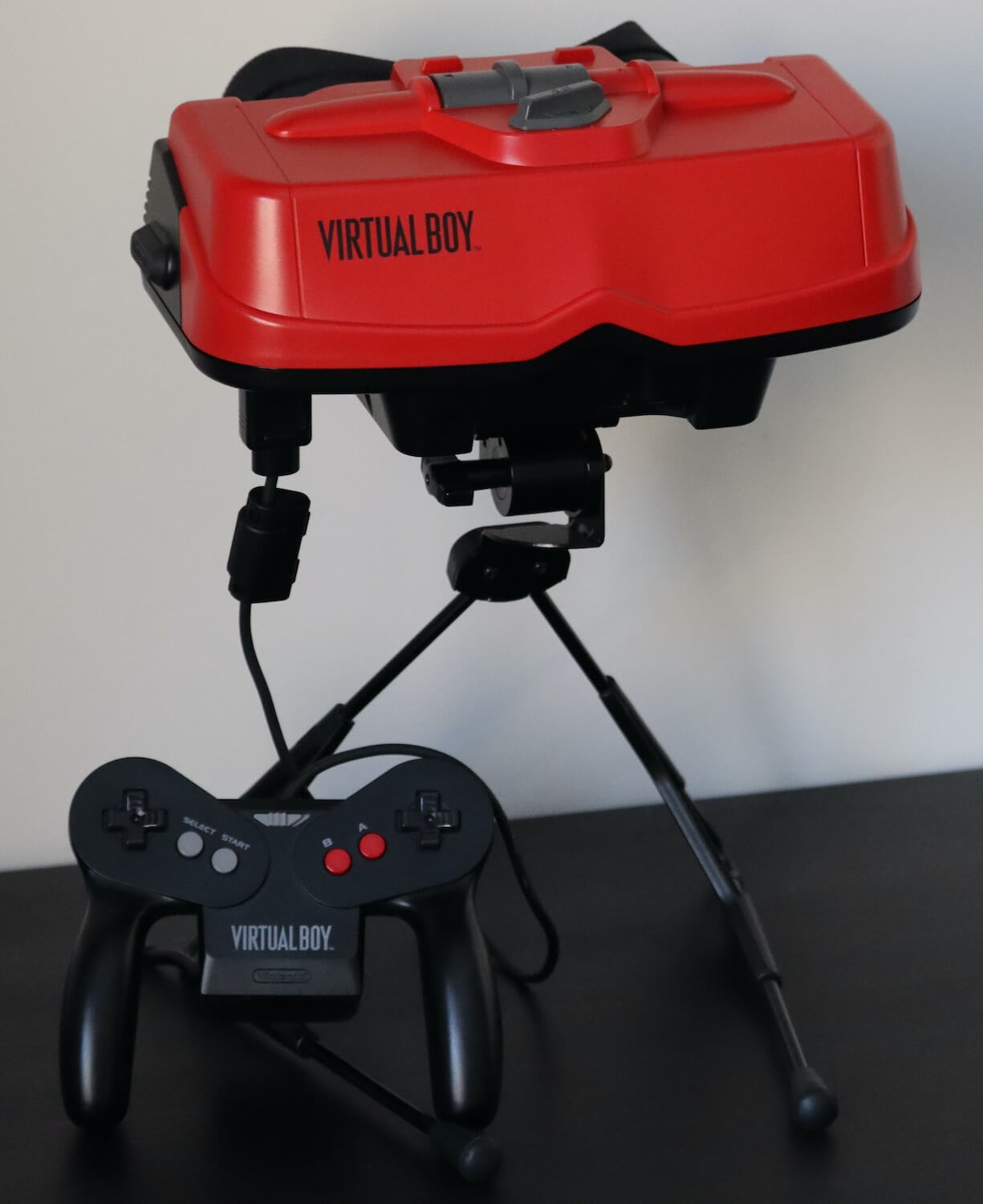
Released on 21/07/1995 in Japan and 14/08/1995 in America.
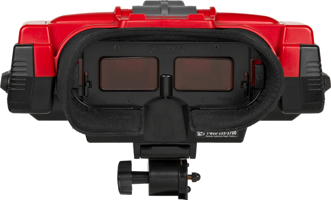
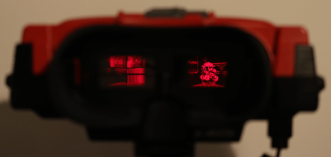
Users are meant to look through the eyepieces.
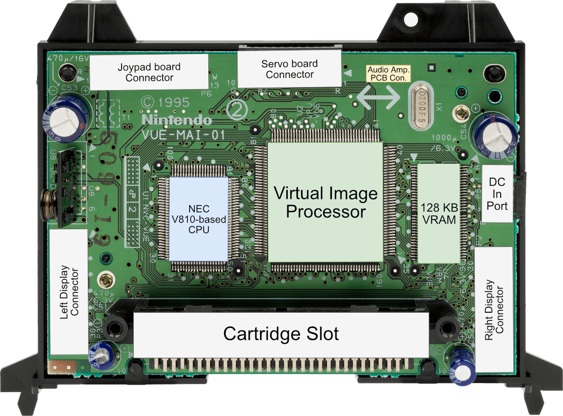
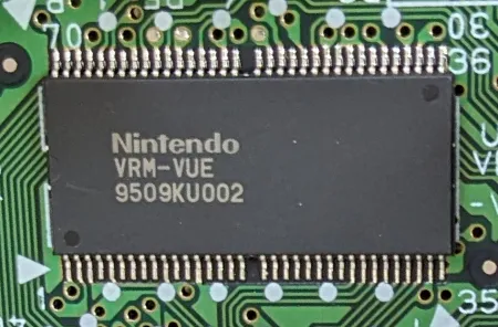
Motherboard
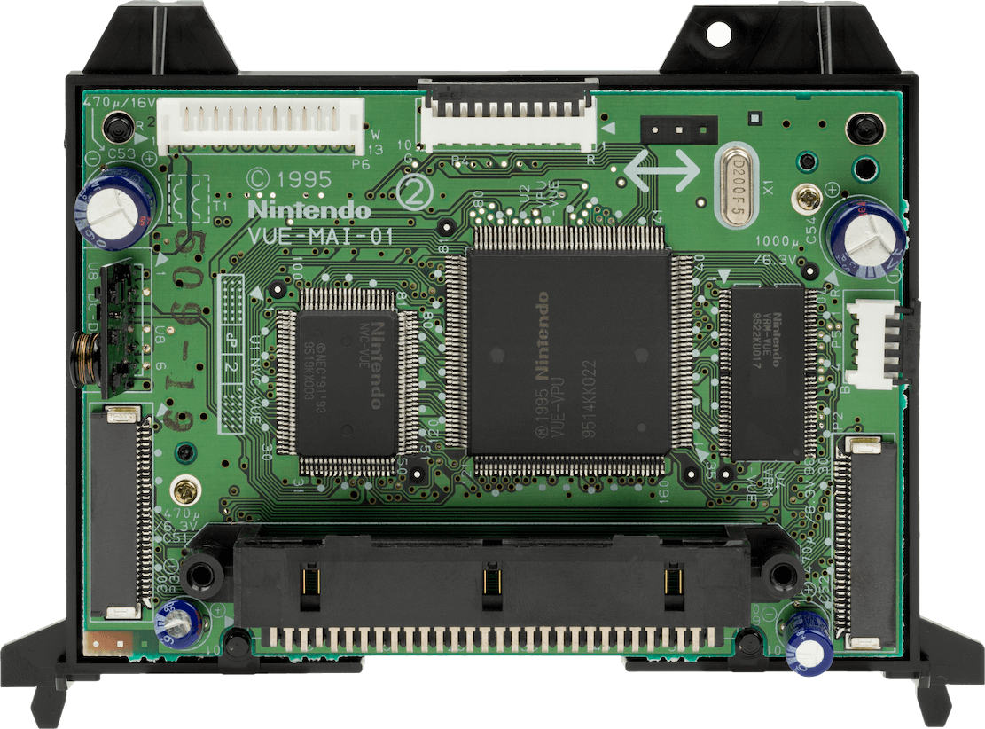
Not to be confused with the 'Servo board', which the motherboard connects to.
The Virtual Sound Unit chip, 128 KB of DRAM, and 64 KB of PSRAM are fitted on the back.
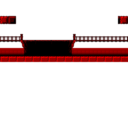
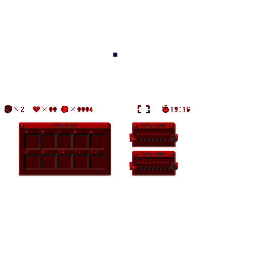
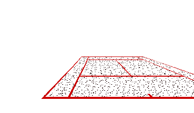
Diagram
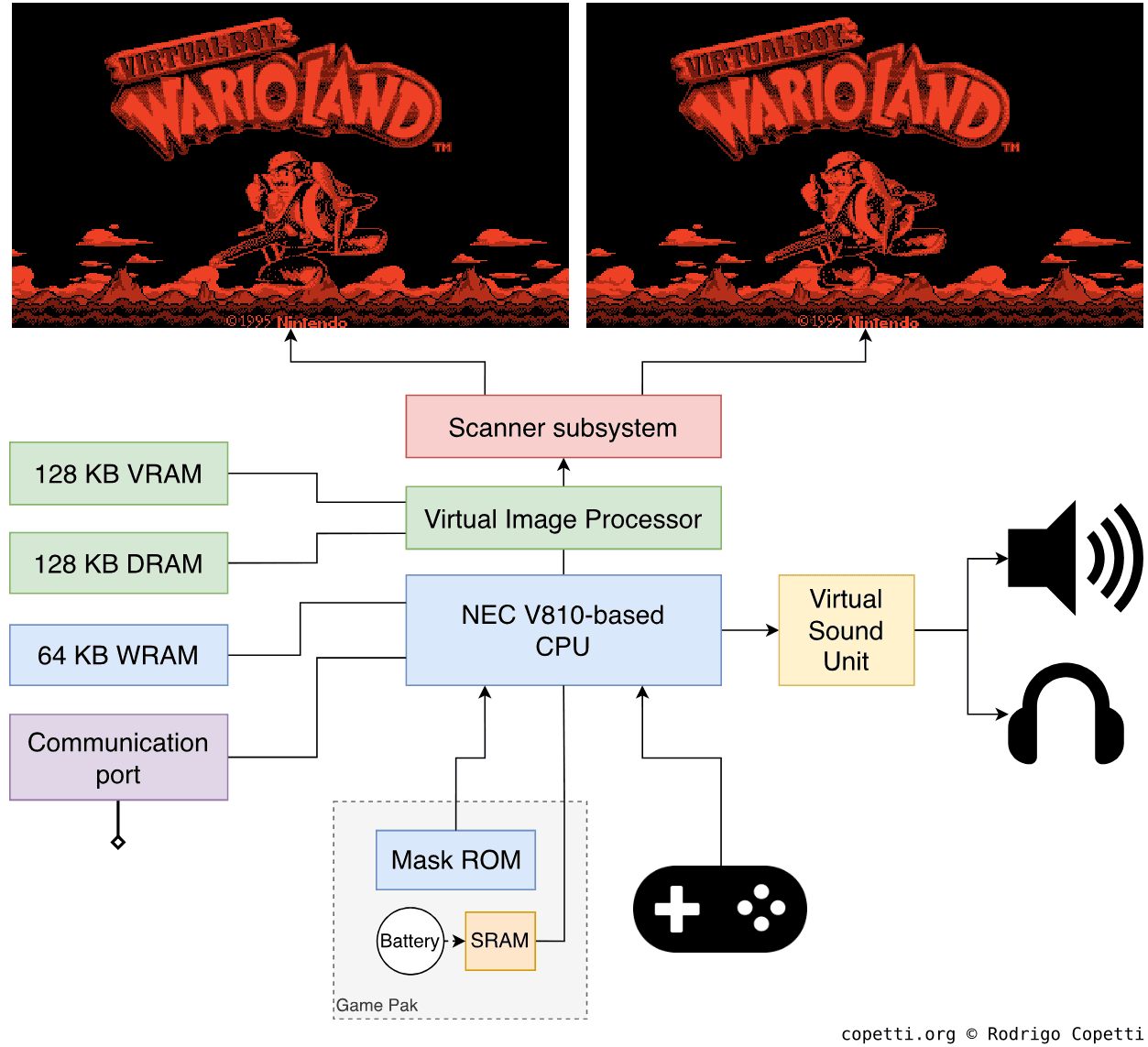
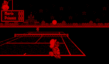
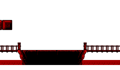
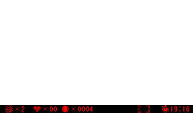
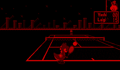
Notice how the two screenshots have their background scenery slightly shifted horizontally.
A quick introduction
A console often summarised by its short lifespan and limited colour space. While technically correct, I believe these attributes tend to overshadow other surprising properties.
In this article, I invite readers to learn more about its internal features - many of which gained predominance in the market only after the Virtual Boy’s discontinuation.
Display
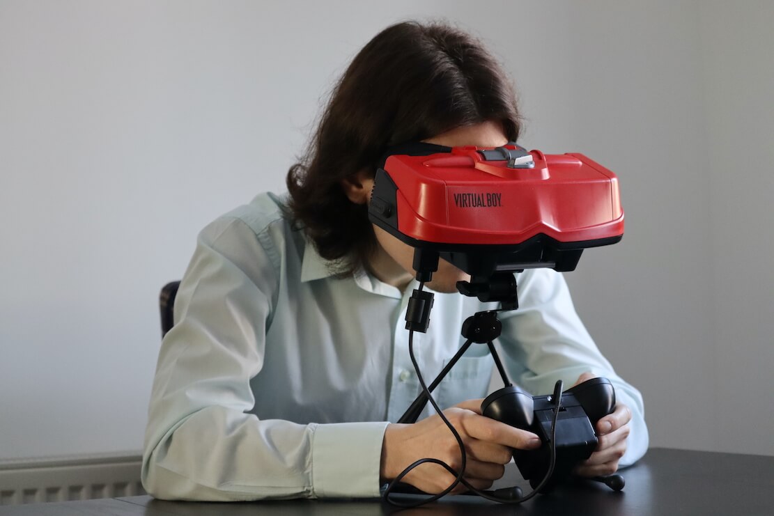
The entire system is a curious feat of engineering. Externally, it resembles a bulky VR headset mounted on a bipod. The player must position their head close to the eyepiece to see the game in action.
Internally, it’s a whole different story (and a very complicated one). For this reason, I thought it would be better to begin by explaining how this console displays images, and then delve into its internal hardware.
Projecting an image
Once you switch on the Virtual Boy, you will see two monochromatic red pictures (one for each eye) through the eyepiece. So far, so good? Well, here is the interesting part: this console doesn’t have a screen. What you’re seeing is more of an illusion, so let’s take a closer look at what’s really going on.
The topics involved in explaining this (including optics, visual phenomena, and so on) may seem complex at first, so I drew many diagrams to make this section a little more immersive.
Scanner
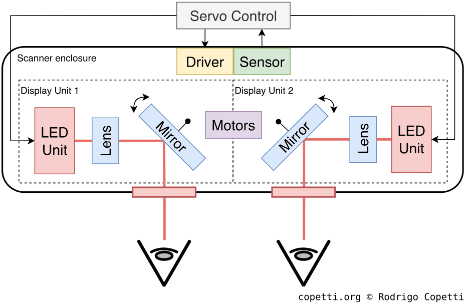
The large volume of this console is attributed to the scanner, which occupies a significant part of the interior. The scanner is the area of the Virtual Boy responsible for displaying images. It’s composed of two display units, each of which independently projects a frame (giving a total of two frames, one for each eye).
A display unit is where all the ‘magic’ happens. It consists of the following components:
- An LED unit: Contains 224 red LEDs stacked vertically, along with the necessary circuitry to control each one.
- A lens: Refracts light from the LEDs.
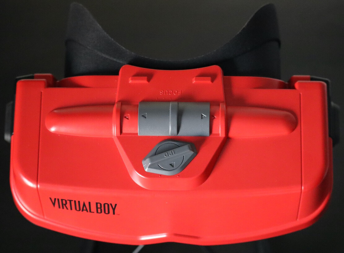
- At the top of the Virtual Boy’s casing, there is a focus slider used to shift the lens closer to or farther from the LEDs. This allows the user to adjust the console according to their focal length (preventing blurry images).
- A mirror: Reflects light from the lens and directs it to the user’s eyes. Furthermore, this component oscillates continuously, thanks to a voice coil motor connected to it. The motor is controlled by the servo control, a separate board that sends electrical pulses at 50 Hz.
- All in all, this is a very complex and fragile area of the console. So, an additional photo interrupter (a type of photosensor) is installed. The interrupter reports the oscillation observed from the mirror to the servo control, which in turn monitors and applies the necessary corrections.
Next to the focus slider is an IPD dial (a knob-shaped switch), which adjusts the distance between the two display units. This is done to adapt the displays to the user’s interpupillary distance.
Mechanics
 Animation available in the modern edition
Now that we have each component identified, let’s take a look at how the Virtual Boy manages to present images to our eyes.
If you haven’t noticed before, there isn’t a dot-matrix display to be found, so how come we can see two-dimensional images through the eyepiece? Similarly to a CRT monitor, the display units exploit the way we perceive images:
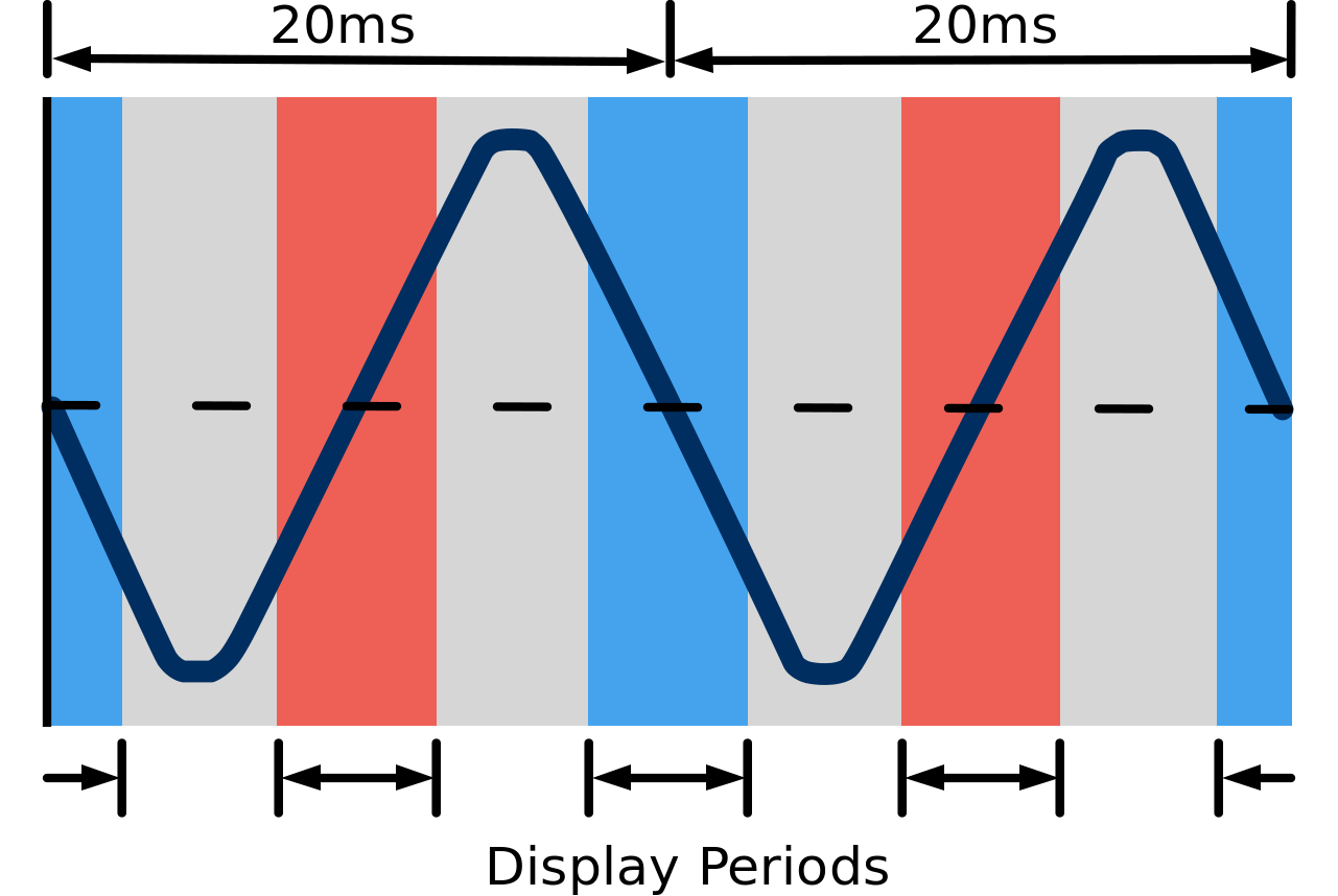
- The oscillating mirrors enable a single column of LEDs to shift horizontally across our field of view. The angle of the mirror is strategically directed to project the LEDs across 384 distinct ‘column positions’ (distributed across our field of view).
- Because human vision is logarithmic and the mirror oscillates at 50 Hz (each period takes 20 ms), we end up perceiving 384 columns of LEDs illuminating at the same time until the mirror stops oscillating. This is the result of the afterimage effect.
- All of this is carefully synchronised with the LED controller, which updates each individual LED as the mirror moves slightly. Thus, we end up perceiving a full picture coming from the eyepiece.
In reality, some conditions must be met for these principles to work:
- The LEDs must only operate when the angular velocity of the mirror is stable (in other words, when the mirror is not changing direction). This can be thought of as the active state of a CRT monitor.
- Building on the previous point, the angular velocity of the mirror doesn’t remain constant in practice. As the mirror cannot change direction instantly, ‘stable’ periods are subject to forces that disrupt its velocity. To manage this, the Virtual Boy stores a list of values in memory called Column Table, which specifies how much time to allocate for each column interval. This helps balance excessive and insufficient periods of ‘LED column’ exposure.
- Finally, let’s not forget that this entire process occurs twice, as there are two display units (one for each eye). Unfortunately, both units can’t draw energy and data at the same time, so each one operates at different display periods (out-of-phase, 10 ms apart). We don’t notice this, yet another illusion!
Display
 Animation available in the modern edition
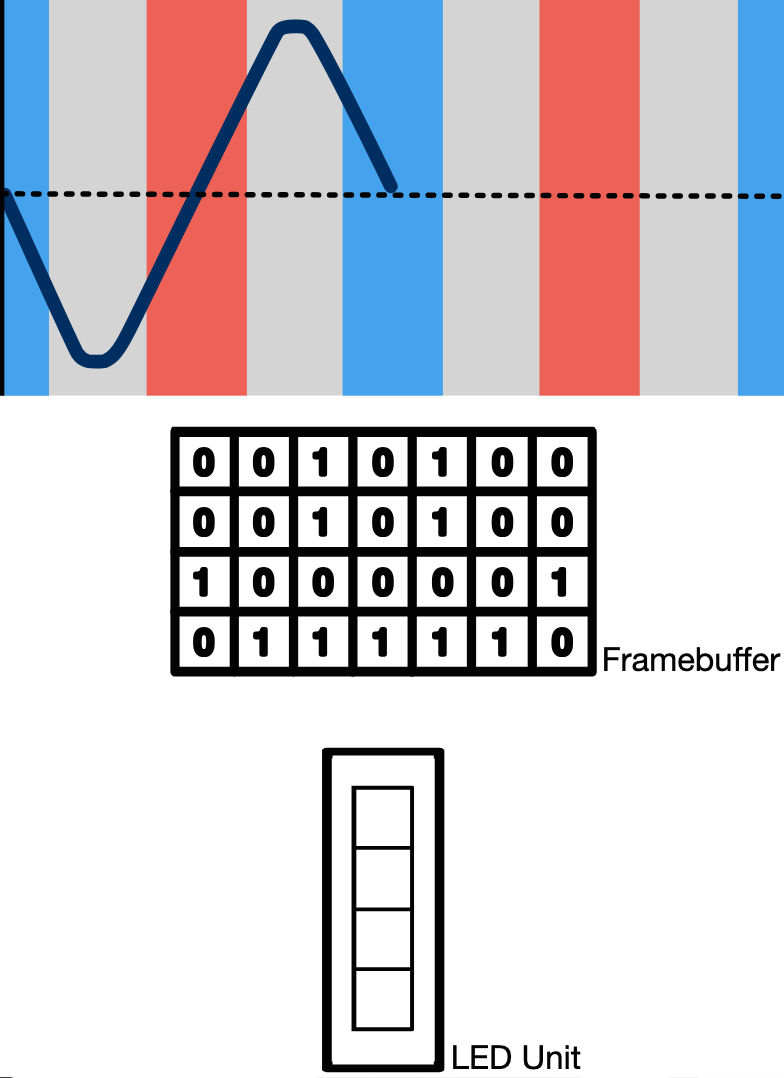
Contrary to previous video chips modelled on CRT displays (e.g. the PPU and VDP), the Virtual Boy does not render graphics on-the-fly. Instead, its graphics chip sends the processed frame to a frame buffer in memory. Then, each column of the frame is transferred to the LED array for display.
When the servo board determines it’s time to display, the graphics chip will transmit columns of pixels from the frame buffer to the 224 vertically stacked LEDs, in a carefully synchronised manner. As a result, the LEDs display 384 columns during the display period, giving the console a ‘screen resolution’ 384x224 pixels.
Moreover, we need to store two frame buffers, since each one will go to a different display unit. The graphics subsystem also employs double-buffering and other quirks (outlined later in the ‘Graphics’ section). So, for now, just remember how a digital frame is sent to the LEDs.
Active periods
 Animation available in the modern edition
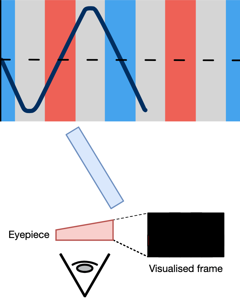
As a consequence of this design, there will be periods of:
- Active Display: During this time, the LEDs are pulling an image from the frame buffer and nothing can disrupt it.
- Active Display 2: Identical to the previous phase, but now the second display unit is active.
- Drawing idle: A period in which none of the LEDs are operating and the mirror’s angular velocity is unstable.
This cycle repeats 50 times per second (hence the 50 Hz refresh rate), meaning that for each frame, the CPU and GPU have approximately 10 milliseconds to update the picture the user will see. In practice, Nintendo’s engineers implemented a more sophisticated solution. I will elaborate further in the ‘Graphics’ section, but for now, I hope you got a good understanding of how the Virtual Boy cleverly managed to generate visuals using inexpensive hardware.
Closing comments
This has been a brief explanation of how optics can transform a single vertical line into a picture. If you own (or have read about) the Virtual Boy, you may be wondering when the three-dimensional imagery comes into play. I want to clarify that none of the previous explanations relate to that effect. I mention this because in the past I’ve seen claims suggesting that the oscillating mirrors are the cause of the ‘depth perception’ effect. However, based on the information I’ve gathered throughout this study, I believe that assertion is inaccurate.
That being said, I think it’s time we delve into the 3D phenomenon…
Producing a third-dimensional vision
During the marketing campaign of the Virtual Boy, there was a lot of fanfare regarding the console’s ability to project a ‘3D world’. I’m not referring to images with 3D polygons stamped (as seen on the other fifth-generation consoles), but rather to the actual perception of depth.
In a nutshell, the Virtual Boy relies on stereoscopic imagery to achieve that illusion [1] [2]. Overall, this system not only toyed with our vision to project a complete image, but also made certain drawings appear closer or further away than others!
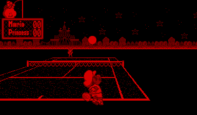
The technique employed is very simple: each of the two frames displayed (one for each eye) contains elements slightly shifted horizontally. So, when viewed with both eyes, these shifts create the illusion that some parts of the image are nearer than others. The perceived depth depends on the direction in which the elements are offset.
Objects shifted towards the centre of the viewer’s eyes (moved right in the left frame, and left in the right frame) appear closer; those shifted away from the centre appear further away. Finally, elements with no horizontal shift are perceived as being between the two extremes. This approach is known as stereoscopic parallax.
One of the drawbacks of stereoscopy is eyestrain. This was alleviated by the fact that games provided an ‘automatic pause’ feature, which reminded the user to take breaks every 30 minutes. Nintendo also included various warning messages in their packaging and documentation to help prevent serious conditions. That said, there was no option to disable the 3D effect.
CPU
Alrighty, back to the digital architecture, let’s see now how games construct the frames and music you see and hear.
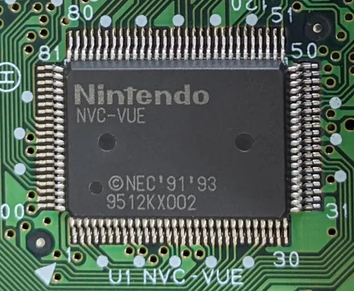
For the CPU, Nintendo employed a customised version of the NEC V810, operating at an impressive 20 MHz (considering the SNES averaged at 1.79 MHz and the GameBoy ran at 4.19 MHz, imagine what this one’s capable of!). The company refers to it as NVC because the chip shipped with the Virtual Boy combines a V810 core with several additional components, which we’ll examine in the next paragraphs.
To start with, the V810 is part of the V800 CPU family that NEC designed for the embedded market [3] [4]. While this CPU wasn’t as popular as the competition (such as the MIPS series or the Motorola 68000) it does offer a range of cutting-edge functionality, specifically:
- The V800 series Instruction Set Architecture (ISA): A RISC instruction set that mixes 16-bit and 32-bit instructions.
- Thirty-two 32-bit registers: The V810 is a complete 32-bit CPU and the registers are well aligned to that architecture.
- As common with RISC CPUs,
r0is always zero.
- As common with RISC CPUs,
- A 32-bit address bus: Enabling to access up to 4 GB of memory, an enormous amount for its time.
- A five-stage pipeline: See a previous article for a detailed explanation of instruction pipelining. Notably, while other systems debuted with three pipeline stages, this one went straight for the five.
- To avoid hazards, NEC resorted to hardware interlocks to stall the pipeline automatically.
- 1 KB of L1 Cache for instructions.
- Interestingly, you won’t see another ‘cached’ handheld from Nintendo until the Nintendo DS arrives nearly a decade later!
This was exceptionally sophisticated for a portable console in 1995, but Nintendo went even further by incorporating additional resources:
- I/O interfaces: These handle the communication with proprietary accessories.
- 16-bit external bus: The V810 can be configured with either a 16-bit or 32-bit bus. Well, Nintendo’s engineers opted for the former.
- This introduces some penalties (i.e. wait states) with 32-bit memory transfers, but as you’ll soon see, programs weren’t that demanding.
- A timer: This is just a 16-bit counter.
- A wait control: Stalls the CPU depending on the external bus accessed. This is because the V810 treats all memory as uniform. In practice, accessing the Game ROM is slower than, let’s say, internal RAM. So, this component corrects the timings accordingly.
While all of this seems fine and dandy, it does come at a big cost: six AA batteries. This likely explains why companies clung to older technologies in portable devices, at least throughout the 90s.
Memory access
32-bit addresses look very tempting on paper, but if the system won’t utilise anything close to 4 GB of memory locations, then it’s a huge waste of resources. For instance, even though the upper address lines remain unchanged, they are still decoded during every memory read.
So, for good reasons, Nintendo cut down to 27-bit addressing. This means that up to 128 MB of memory can be accessed instead. The system still uses 32-bit words for addresses, but the upper 5 bits are discarded. As a result, some regions of the memory map are mirrored.
Having said that, the memory map layout enables the CPU to access the majority of the components that make up this system. This includes [5]:
- 64 KB of RAM for general-purpose use. For that reason, Nintendo calls it ‘Work RAM’ or ‘WRAM’.
- The type of chip fitted is called PSRAM (short for ‘Pseudo-Static RAM’ or ‘Pseudo-SRAM’), which incorporates self-refreshing Dynamic RAM (DRAM). This setup is both faster and more energy-efficient than the traditional low-cost DRAM.
- The cartridge ROM and any onboard RAM (if present).
- The sound chip.
- The graphics chip, along with its dedicated memory.
- I/O interfaces and their respective registers.
This is as far as the CPU goes, now it’s time to see what you can do with it!
Graphics
Let’s recap the key requirements for the proper display of graphics:
- The Virtual Boy must show two distinct frames.
- Each frame has a resolution of 384x224 pixels.
- The colour palette consists of various shades of red, plus black/transparent (representing the LED in off state).
- The scenery requires parallax applied to achieve depth.
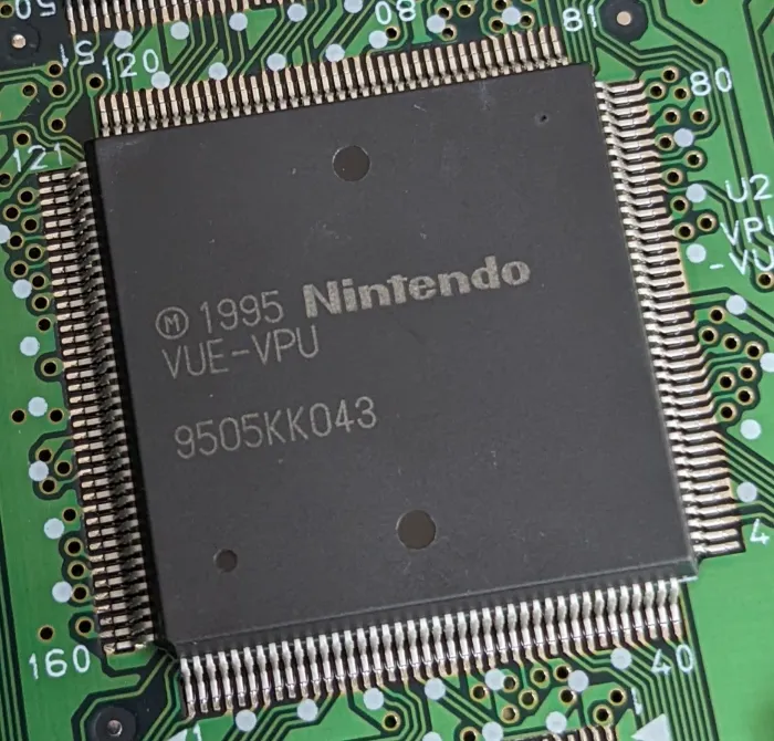
Good news is that all of this is accelerated by the Video Image Processor or ‘VIP’, a dedicated chip developed by Nintendo. It borrows some features from the old PPU, but I consider it a clear departure from its predecessors.
Architecture
At first glance, the VIP might appear to be just another tile engine, but it’s much more advanced than that. For starters, it not only processes graphics data but also controls the scanner.
Moreover, whereas classic tile engines rendered graphics per scan line, the VIP employs a frame buffer architecture, storing the final frame in memory (as a bitmap) and then sending it for display. This is closer to the modus operandi of modern 3D renderers. In fact, the Virtual Boy went a step further by implementing a form of page flipping, in which two frame buffers are allocated per display unit, allowing the scanner to read from one while the VIP writes to the other. All of this helps to prevent image tearing.
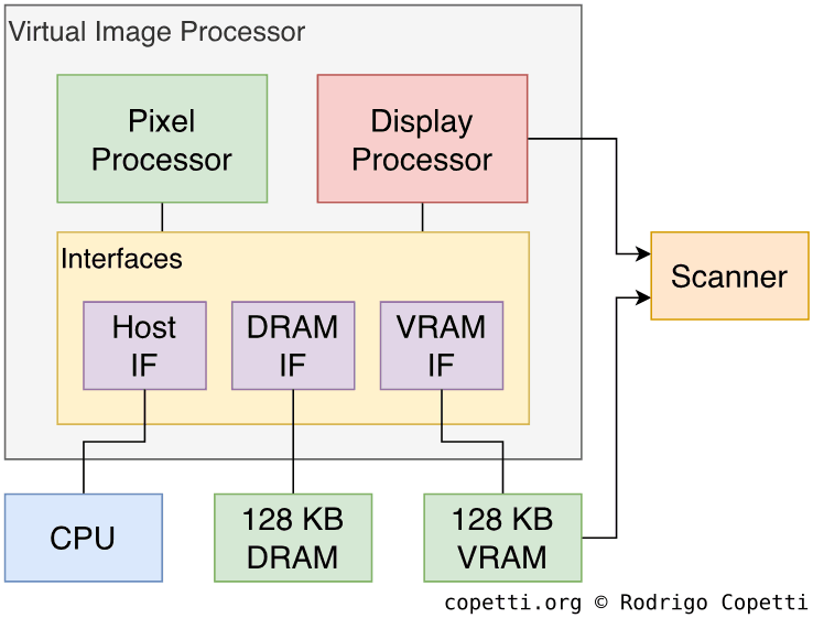
Moving on, you can divide the VIP into three main areas:
- The Pixel Processor or ‘XP’: Generates backgrounds and sprites, much like the classic PPU. It writes the final processed bitmap to the frame buffer area in memory.
- The Display Processor or ‘DP’: Controls the scanner and sends a frame buffer for display.
- The interfaces: Provide access to two memory blocks - 128 KB of Video RAM (VRAM) and 128 KB of DRAM [6]. The interfaces also arbitrate access between VRAM and the CPU (called the ‘Host’, from the VIP’s perspective).
Overall, the pipeline is straightforward:
- The CPU sets up the VIP by writing to its internal registers and filling up VRAM and DRAM with the required materials.
- The XP then generates frame buffers, which are stored in VRAM.
- The DP selects the appropriate frame buffer and transmits it to the scanner for display. This is done by copying the frame, four columns at a time, into a small buffer area in VRAM known as Serial Access Memory or ‘SAM’, which is automatically broadcast to the scanner.
Organising the content
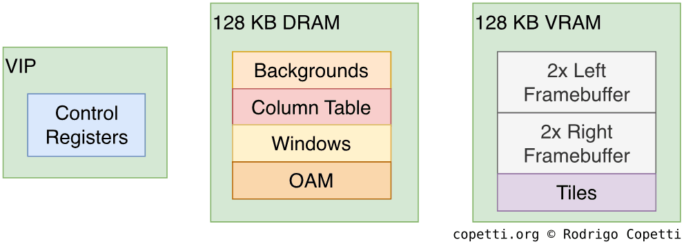
From the developer’s side, there are two blocks of memory used by the XP and DP:
- 128 KB of DRAM for storing graphics data to be processed.
- 128 KB of VRAM for storing the frame buffers accessed by the DP.
- As there are two display units, the system requires a total of four frame buffers. Each generated bitmap is 24 KB wide, so developers need to allocate 96 KB of memory. The remaining 32 KB is used by the XP to store tiles.
Notice that those 128 KB of VRAM are ‘real’ dual-ported DRAM [7], not merely a block of RAM reserved for graphics (which Nintendo also calls ‘VRAM’). Dual-ported DRAM enables two devices to read from it at the same time, which explains why the XP can write to VRAM while the scanner is reading from it concurrently.
Additionally, Nintendo fitted a particular VRAM chip that is nowhere to be found in any off-the-shelf catalogue. There is limited documentation about it, but according to details outlined in the patent application [8], Serial Access Memory (SAM) might be stored in a separate area within this chip. SAM is presumably made of Static RAM (SRAM) and contains extra circuitry that allows the scanner to pull 16 bits simultaneously [9].
Constructing a frame
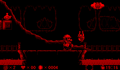
Let’s now dive deeper and see how a single frame is drawn on the Pixel Processor. To illustrate this, I’ll borrow the assets of Virtual Boy Wario Land.
Before we start, I strongly recommend reading about a previous tile engine, as it will reinforce the old concepts.
Tiles


We have previously seen how traditional tile engines build their layers using 8x8 bitmaps. In the case of the Virtual Boy, tiles (originally called ‘Characters’) are stored in VRAM within an area known as the Pattern table. Each tile occupies 16 bytes (as 2 bits are allocated per pixel), so there is enough space for 2048 tiles.
In terms of colours, developers can compose eight colour palettes, four for background graphics and another four for sprites.
One may wonder about the purpose of colour palettes if the LEDs are monochrome. Well, this setup enables developers to use different shades of red. These shades are obtained by altering the brightness of the LEDs.
The brightness settings are stored in two registers, which are then referenced in the palettes, effectively creating a catalogue of different shades. All resulting palettes contain:
- Two custom reds.
- An additional red automatically calculated from the sum of the previous two.
- The ‘transparent’ colour.
Backgrounds

The background layer is very simple: tiles are selected to form a 512x512 map (64x64 tiles, resulting in 4096 tiles in total). But that’s not all, because instead of having just a single background layer available… there are 14!
Each individual background layer is called a segment. A single segment occupies 8 KB of memory, with each tile reference storing horizontal/vertical flip attributes and a palette index. Each tile reference consumes 2 bytes of memory.
The Pixel Processor also supports combining multiple segments to generate a larger layer, although only certain combinations are available. The largest mix combines eight segments.
Sprites
Sprites (or ‘Objects’, as Nintendo calls them) are single tiles with independent coordinates, but they require more memory.
There is an area in DRAM called Object Attribute Memory (OAM) with 8 KB of allocated memory, in here sprites definitions are stored. Each definition occupies 8 bytes, allowing for up to 1024 sprites to be declared.
Each sprite includes the following properties:
- X and Y coordinates.
- A flag determining where it is displayed (left screen, right one, or both).
- The parallax offset, which applies automatic parallax. This makes each screen display the sprite with a slight horizontal shift.
- This value is signed: a positive value makes it look far away, whereas a negative value makes it appear closer.
- The index of the tile used.
- Horizontal/vertical flip.
- The palette index.
You’ll notice there are no example screenshots included in this section; the following paragraphs explain why.
Window


The layering system may seem simple at first. After all, the VIP provides background layers and a sprite layer. So, what else would be needed?
In reality, to display any of the previously mentioned layers, they must be placed into a container called Window (also referred to as ‘World’). A window is the actual plane that gets rendered to the screen, populated with layers previously constructed. There are 32 windows available which overlap to form the final frame, and each window definition occupies 32 bytes.
Windows provide various rendering modes. Developers can select a background or sprite layer and display it as it is. To do so, the window must be set to Normal mode or Object mode, depending on the layer type.
However, the chip offers additional modes that apply extra effects to background layers:
- Line Shift Mode: Individual rows of pixels can be shifted horizontally. This resembles the good ol’ effects triggered during horizontal interrupts.
- Affine Mode: As the name indicates, this enables affine transformations! In other words, scaling, rotation, or a combination to simulate perspective projection [10].
Result
After setting everything up, the Pixel Processor begins rendering the 32 windows. Once it is done, the final frame is placed in the frame buffer region. This process is then repeated for the other display unit as well.
Since the system employs a double-buffered design, the Display Processor always fetches the frame buffer that the Pixel Processor is not currently manipulating, preventing screen tearing. During the next active period, the Pixel Processor overwrites the frame previously displayed by the Display Processor, and the cycle continues.
If there is minimal content to render (i.e. only a few windows are used), there will be long gaps between writing to the frame buffer and the Display Processor retrieving it. This enables the CPU to make extra changes to the frame if needed. The VIP is also prepared for this: the CPU can set up interrupts to monitor various states of the VIP, including this scenario.
On the other hand, if too many affine windows are rendered, the Pixel Processor may miss the deadline, resulting in frame drops. Luckily, interrupts are available to detect this condition as well. In any case, the official documentation provided the timings for each layer type.
Creative content
As you can see, there is a lot more technology in this console than meets the eye.
Initially, I believed the Game Boy Advance was the first portable console capable of reproducing the acclaimed Mode 7 effect from the Super Nintendo, nearly 11 years later. It turns out it was the Virtual Boy that achieved this first, just five years later. But it can go even further: as we’ve seen before, affine transformations on the Virtual Boy could be applied to all 32 layers (albeit with some limitations).
Furthermore, all these new functions operated in tandem with parallax effects, something that the VIP also took care of.
One can’t help but wonder what kinds of games might have emerged had this console endured just a little longer, long enough for developers to get more comfortable with this hardware.
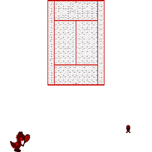
Another noteworthy feature was the CPU’s ability to alter the frame buffer directly, providing developers with the flexibility to construct their own renderer when the VIP wasn’t enough for them. This is what some games relied on to showcase their innovative graphics. For instance, Red Alarm implemented a scenery composed of 3D wireframes rendered by the CPU.
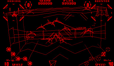
Unfortunately, fundamental challenges such as visible surface determination were not always addressed properly. I speculate this was due to the limitations of the CPU. In any case, this resulted in scenes turned into tangled meshes of elements, which made it difficult for the player to distinguish which objects were behind others.
Audio
Imagine taking the Game Boy’s wave channel, multiplying it by five and adding a noise channel: that’s pretty much the offering of the Virtual Boy’s sound chip. It can also be regarded as a sibling of the PC Engine’s audio system.
In the motherboard, there is a chip called Virtual Sound Unit (VSU) that provides the sound capabilities. The VSU relies on internal RAM to store five wavetables and a register file to configure each of the six channels available (five waves and one noise).
Registers are 8 bits wide, while the internal RAM is connected to a 6-bit data bus. The CPU still treats 6-bit words as a single byte, discarding the upper two bits.
Each wavetable is made of 32 PCM samples encoded in 6-bit values. Channels support panning control (using a volume level value, ranging from 0 to 15, for each left and right) and an 11-bit frequency control.
Each channel also includes basic envelope control, allowing the volume to grow or decay over time.
The fifth channel offers more effects, namely a sweeping function to progressively shift the frequency, and a modulator to alter the waveform based on values stored in the internal RAM.
Meanwhile, the sixth/last channel can only output noise.
Output
The mixed output is stereo, with a 10-bit resolution and a sampling rate of 41.7 kHz. It’s also worth pointing out that the console has stereo speakers, so you don’t have to wear headphones to enjoy this!
I/O
The Virtual Boy is technically classed as ‘portable’, so don’t expect game-changing accessories (pun intended). That said, there are still a few extras worth noting.
Available interfaces
Internally, nearly every component is directly connected to the CPU, with the exception of some areas handled exclusively by the VIP.
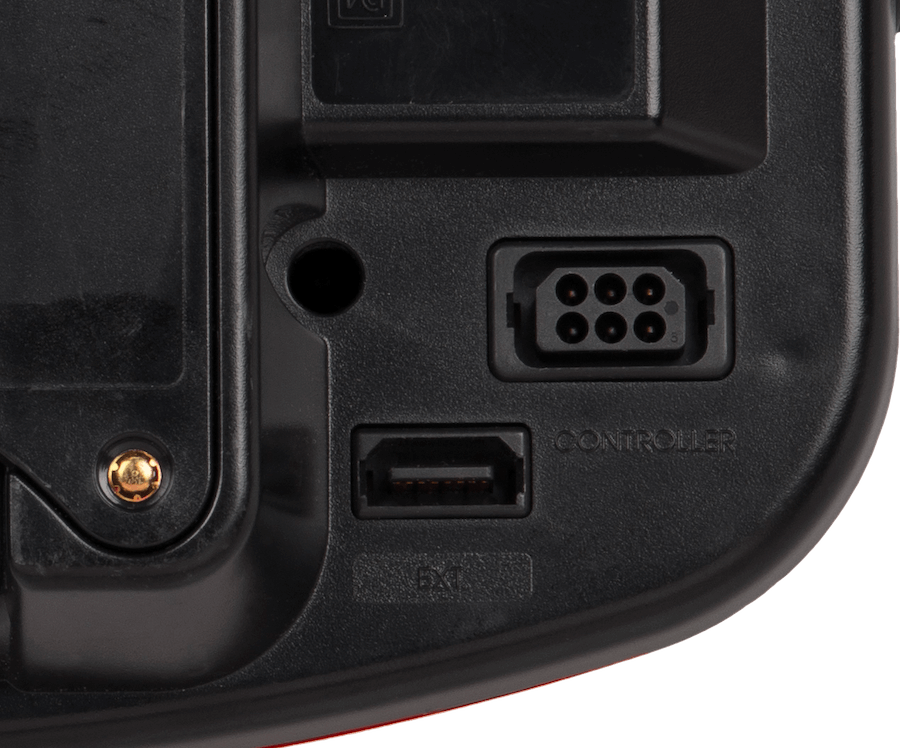
Externally, the console features two connectors for accessories:
- The Serial Port: Connects the controller, with data transferred in a serial manner (one bit at a time) [12]. The interface adapts the transmission into a 16-bit value for the CPU to read. In turn, the CPU interprets each bit place as a button input. Interrupts can also be set up to notify the CPU the instant any key is pressed.
- One pin on this connector supplies 5 Volts from the controller to the console, in that direction. This is actually used to power the console!
- The Communications Port: Whilst not an accessory per se, this port enables the communication between two Virtual Boys. This reminds me of the Game Boy’s Link cable. The two Virtual Boys communicate in a master-slave manner using serial data streams.
- Unfortunately, no game ended up using this feature. Yet, this really makes you wonder what kind of multiplayer functionality was Nintendo envisioning.
The provider
The controller of the Virtual Boy is very peculiar compared to the rest of the console line. It is somewhat similar to the Super Nintendo one, albeit without the ‘X’ & ‘Y’ buttons, featuring a larger grip and an extra D-Pad on the right-hand side. Most notably, it was designed to prevent being looked at during gameplay.
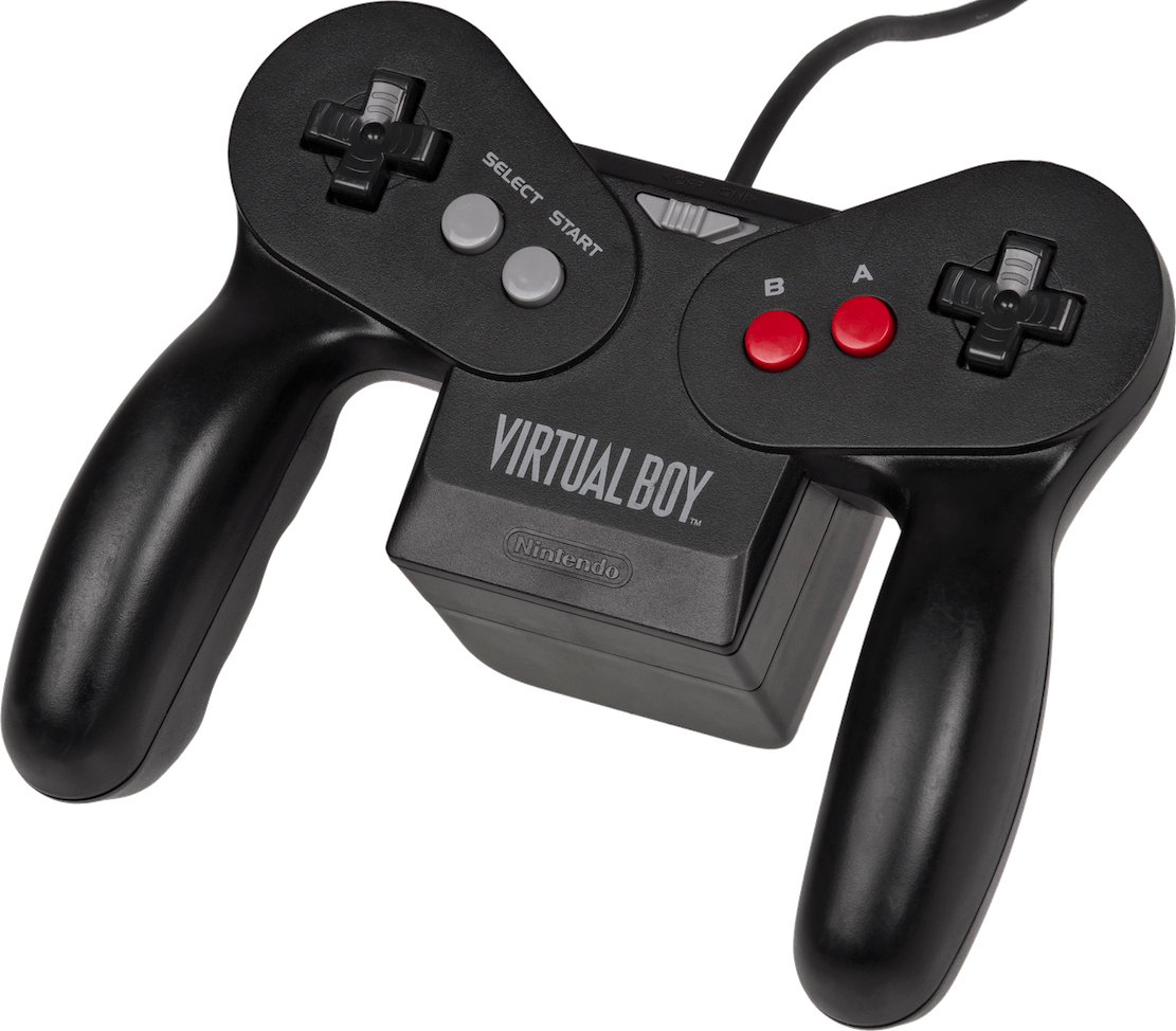
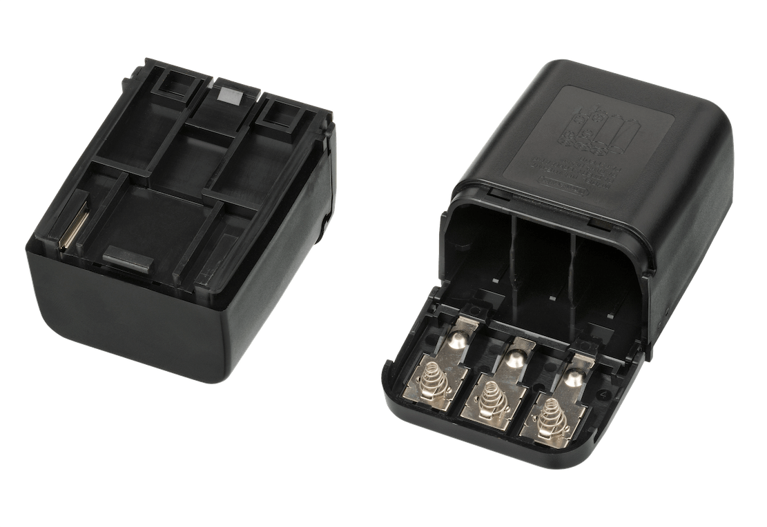
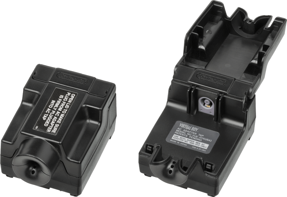
Moreover, the controller was also meant to supply power to the console, so it comes with a removable battery magazine on the back. The cartridge, called Tap, holds six AA batteries. For those users who got fed up with searching for replacements whenever any of the six ran out, Nintendo offered an alternative Tap that connects to an external AC power supply.
I have to admit, when I tried using the Virtual Boy with the AC Tap connected (since hunting for six fully-charged batteries is a pain), playing any game felt like a house of cards - I had to stay mindful of the tangled cables while being unable to look outside the eyepiece. But I guess that’s the price to pay if you’d rather not worry about batteries!
Operating System
The V810 starts execution at address 0xFFFFFFF0H, meaning that when the Virtual Boy is switched on, it seeks instructions at that location. That being said, that address resides within the cartridge ROM, giving the game the upper hand in the initialisation of the hardware.
Also, there isn’t any Basic Input/Output System (BIOS) chip on the motherboard, so no operating system or abstraction layer is present to simplify operations.
House chores
For this reason, Nintendo instructed developers to perform several chores to ensure the proper functioning of this console, including:
- WRAM becomes usable only after 200 microseconds (0.0002 seconds) following the console’s startup. The documentation includes a list of steps that games must follow to account for this delay.
- Many years later, unofficial sources claimed that this was an erratum on Nintendo’s part, and that it is the VIP’s DRAM that actually requires waiting, as the datasheets corroborate [16].
- The game must populate the Column Table. To recall previous explanations, the ‘active display’ period is subject to a variable angular velocity. To prevent certain columns of the frame from appearing narrower than others, games fill a table in DRAM that applies corrections. To make things easier, Nintendo provided a default Column Table in their Software Development Kit (SDK), which games could use.
- The table can also be amended at any time during gameplay and, since it consequently controls the amount of LED emission, the table also serves as a mechanism for adjusting the amount of brightness per column.
Games
One may assume that game development would just inherit the same tools as the Game Boy (namely, plain assembly), but it turns out Nintendo and NEC invested in new technologies to modernise and accelerate third-party development.
Development ecosystem
Game studios had the option to purchase a development kit from Nintendo, which included a fully equipped debugging station, toolchain, and plenty of documentation.
The hardware kit was called VUE Development System (‘VUE’ was the codename of this console). It was a PC-like tower that housed the Virtual Boy’s internals, plus 4 MB of RAM (expandable to 8 MB!). It connected to a headset resembling the retail Virtual Boy, and a retail controller. To run and debug software, the development kit featured an interface board that communicated with an IBM PC via SCSI. To operate the equipment, developers required an IBM PC/AT (or compatible clone) with an Intel 80386 CPU, 2 MB of memory and MS-DOS installed.
The software kit included a linker, assembler, and debugger. Upon request, Nintendo also offered a C compiler, meaning developers no longer needed to write programs directly in assembly! Altogether, this setup took 1.5 MB of your precious -and noisy- hard disk.
It’s unfortunate that this model of development was later reverted with the release of the Game Boy Color. I presume this was due to the Game Boy Color’s CPU being unable to handle ‘unoptimised’ code from a compiler.
Medium
Game cartridges are referred to as Game Paks, the same name used for the Game Boy medium, though they differ entirely in shape and functionality.
Due to the available memory address space, the ROM can reach up to 16 MB without a mapper. The same applies to external RAM. As with the Game Boy, cartridges may include battery-backed SRAM. Access to the cartridge is handled via a 16-bit data bus.
Come to think of it, 16 MB of ROM is quite substantial for the mid-’90s. After all, the maximum size of a Game Boy ROM was just 128 KB (without a mapper)! Then again, let’s not forget this console uses 32-bit addressing, so each address occupies 4 bytes. That’s twice the size of Game Boy’s 2-byte addresses, which adds up to the space requirements.
Rules
Due to safety concerns, Nintendo ordered developers to include a set of frames aimed at mitigating eyestrain and other conditions associated with prolonged screen use.
Thus, all games displayed a ‘read the instructions’ warning, an alignment guide, and an automatic pause dialogue.
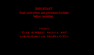


These screens appear after the console is switched on:
- The first ‘orders’ the user to read the instructions manual before continuing.
- The second is some sort of ‘test card’, used to properly adjust the IPD dial and focus slider.
- The third prompts the user to choose whether they’d like to receive a reminder to take a break every thirty minutes.
The first and third screens were often customised to match the game’s theme.
I don’t think Nintendo imposed similar guidelines again until the release of the Wii.
Anti-Piracy and Homebrew
The fact that Nintendo created yet another variation of the Game Pak allowed them to retain control over distribution. Although, since this console never took off, bootleggers likely didn’t bother.
Furthermore, the console lacks both copy protection and region-locking mechanisms. Games imported from America and Japan will work on either console. Also, assuming someone is willing to manufacture their own Game Paks, homebrew development is also possible without restrictions.
The last time I checked, Flash carts were theoretically possible, but only a handful reached commercialisation in recent years.
That’s all folks
Throughout this series, we’ve seen all kinds of systems, some with modest CPUs but impressive synergies, others with questionable hardware but beautifully packaged. This particular case, however, presented an interesting proposal: the CPU was far from limited, and the graphics hardware was up to the task. The sound wasn’t outstanding, yet it remained comparable to other handhelds of the time.
So, why didn’t more children play with it? I’m afraid a marketing study is beyond the scope of this article. But from the technical side, I suspect the message simply didn’t land. At the end of the day, nobody cares about affine transformations or a pipelined CPU if all they see is red dots.
I suppose that was my driving motivation for writing this piece: to uncover innovative technology buried in the most unexpected places.
I would also like to thank the Planet Virtual Boy community for helping me with the study. They are currently working on many projects that continue to breathe new life into the Virtual Boy, so I recommend browsing their forum for more insight.
Finally, this marks the final entry in the ‘retro saga’, the next one will return to (relatively) modern renderers - starting with the PSP!
Until next time!
Rodrigo